Abstract: The DS1086 spread spectrum EconOscillator™ can be used to reduce radiated emissions (EMI) without having to increase system costs by adding extra components such as EMI shields, cable shielding, or EMI filters. By dithering the output frequency, the fundamental frequency gets spread across a range of frequencies thus reducing the amplitude of the emission peak. This application note will show how to interface a DS1086 with two common microcontrollers, the 8051 and PIC. Design considerations will be discussed because with the introduction of dither into the system, the system designer should be aware of the effects dither may have on the overall system. In addition to reducing EMI, other advantages of using the DS1086 in place of a crystal oscillator are discussed.
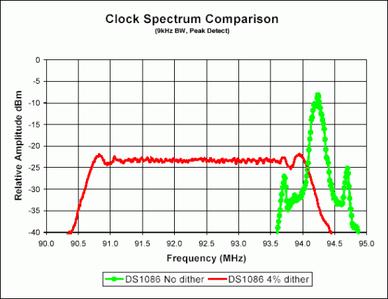
Figure 1 shows a comparison between a DS1086 signal with no dither and a DS1086 signal with 4% dither enabled. The dithered signal shows approximately a 16dB decrease in amplitude. Using 94MHz as an example (for illustration purposes only), the 4% dithered signal will range from 90.24MHz to 94MHz since the frequency is always dithered down. A 2% dithered signal would range from 92.12MHz to 94MHz.

Figure 1. Clock spectrum comparison.
A triangle wave generator injects an offset element into the master oscillator to dither its output. The dither rate (see Equation 1) is based on the master oscillator frequency, which the user can program from 66MHz to 133MHz.

Equation 1.
With a master oscillator frequency of 66MHz, the dither rate of the triangle wave is 16.1kHz. The period is 62.06µs as shown in Figure 2. The peaks of the triangle wave vary between 66MHz and 66MHz - 4% (63.36MHz). Since the dither rate is small, the output frequency looks almost fixed from cycle to cycle.

Figure 2. Dither rate.
In the DS1086, dither is controlled by the J0 bit in the PRESCALER register and enabled when the SPRD pin is tied high. The maximum spectral attenuation occurs when the prescaler is set to 1. The spectral attenuation is reduced by 2.7dB for every factor of 2 that is used in the prescaler. This happens because the prescaler's divider function tends to average the dither when creating the lower frequency. However, the most stringent spectral emission limits are imposed on the higher frequencies where the prescaler is set to a low divider ratio.

Figure 3. DS1086 as a system clock for an 8051 and PIC microcontroller.
For the 2-wire master to communicate with the DS1086, each DS1086 needs to have its own unique device address. To limit the size of the package, there are no external address pins. The device address is set with the three address bits in the ADDR register, A2, A1, and A0 (see Figure 4). The device address factory default is 000b. The DS1086 can be set to any address between 000b and 111b. If multiple DS1086 devices are on the same bus, as shown in Figure 3, their addresses need to be unique. The DS1086 in the 8051 system has a device address of 000b and the DS1086 in the PIC system has a device address of 001b.
Figure 4. ADDR register

Figure 5. Standalone mode.
If the DS1086 will never be programmed in-circuit, even during production testing, then the pull-up resistors are not needed and the signals can be tied directly to the voltage supply. This simplifies the design because there are fewer components needed and software is not required. The disadvantage is that the DS1086 cannot easily be programmed without redesigning the hardware.

Figure 6. Spectrum comparison between DS1086 and a crystal oscillator.
The user can also easily change the output frequency on-the-fly. A programmable oscillator prevents having to purchase numerous crystal oscillators of different frequencies. Also a tank circuit is not needed with an EconOscillator, as it is for crystal oscillators in systems requiring high frequencies.
The DS1086 is also less susceptibility to vibration, has a power-down mode, and is available in a smaller package than some crystal oscillators. The DS1086 is available in an 8-pin 150mil SO package. An 8-pin 118mil µSOP is a future product.
Any questions or comments about this application note can be sent to MixedSignal.Apps@dalsemi.com.
For more information about the DS1086 refer to the data sheet and the following application notes:
Spread Spectrum Output
The DS1086 has the ability to reduce radiated emission peaks. The output frequency can be dithered 2% or 4% below the programmed frequency. Although the output frequency changes when the dither is enabled, the duty cycle does not change.Figure 1 shows a comparison between a DS1086 signal with no dither and a DS1086 signal with 4% dither enabled. The dithered signal shows approximately a 16dB decrease in amplitude. Using 94MHz as an example (for illustration purposes only), the 4% dithered signal will range from 90.24MHz to 94MHz since the frequency is always dithered down. A 2% dithered signal would range from 92.12MHz to 94MHz.

Figure 1. Clock spectrum comparison.
A triangle wave generator injects an offset element into the master oscillator to dither its output. The dither rate (see Equation 1) is based on the master oscillator frequency, which the user can program from 66MHz to 133MHz.

Equation 1.
With a master oscillator frequency of 66MHz, the dither rate of the triangle wave is 16.1kHz. The period is 62.06µs as shown in Figure 2. The peaks of the triangle wave vary between 66MHz and 66MHz - 4% (63.36MHz). Since the dither rate is small, the output frequency looks almost fixed from cycle to cycle.

Figure 2. Dither rate.
In the DS1086, dither is controlled by the J0 bit in the PRESCALER register and enabled when the SPRD pin is tied high. The maximum spectral attenuation occurs when the prescaler is set to 1. The spectral attenuation is reduced by 2.7dB for every factor of 2 that is used in the prescaler. This happens because the prescaler's divider function tends to average the dither when creating the lower frequency. However, the most stringent spectral emission limits are imposed on the higher frequencies where the prescaler is set to a low divider ratio.
Using the DS1086 as a Microcontroller Clock
The DS1086 can be operated in two different modes when used as a microcontroller clock. The modes are processor-controlled mode and standalone mode. These two modes are described in more detail below along with design considerations, which should be addressed when implementing the spread spectrum oscillator with a microcontroller.Processor-Controlled Mode
Figure 3 shows the DS1086 as a system clock for both the 8051 and the PIC microcontroller in processorcontrolled mode. The figure also illustrates how multiple DS1086 devices can be used on a common bus. Each microcontroller is independent of each other although the same 2-wire master controls both microcontrollers.
Figure 3. DS1086 as a system clock for an 8051 and PIC microcontroller.
For the 2-wire master to communicate with the DS1086, each DS1086 needs to have its own unique device address. To limit the size of the package, there are no external address pins. The device address is set with the three address bits in the ADDR register, A2, A1, and A0 (see Figure 4). The device address factory default is 000b. The DS1086 can be set to any address between 000b and 111b. If multiple DS1086 devices are on the same bus, as shown in Figure 3, their addresses need to be unique. The DS1086 in the 8051 system has a device address of 000b and the DS1086 in the PIC system has a device address of 001b.
Figure 4. ADDR register
| REGISTER | ADDR | BINARY | DEFAULT | ACCESS | |||||||
| ADDR | 0Dh | X1 | X1 | X1 | X1 | WC | A2 | A1 | A0 | 11110000b | R/W |
Standalone Mode
The DS1086 can be used as a replacement for a crystal oscillator. Figure 5 shows the DS1086 with an 8051 microcontroller in standalone mode. The PIC can also be used in standalone mode. In standalone mode, the DS1086 can be programmed once, and then the SCL and SDA pins are tied high through a resistor.
Figure 5. Standalone mode.
If the DS1086 will never be programmed in-circuit, even during production testing, then the pull-up resistors are not needed and the signals can be tied directly to the voltage supply. This simplifies the design because there are fewer components needed and software is not required. The disadvantage is that the DS1086 cannot easily be programmed without redesigning the hardware.
Design Considerations
The following questions need to be addressed when using a spread spectrum oscillator as a clock for a microcontroller based system:- How well does the system accept frequency variation?
Most systems that do not require precise timing have no problem with the frequency variation the DS1086 creates. The signal only varies, for example with a 33MHz clock and 4% dither, 1.9ns (1÷31.69MHz - 1÷33MHz = 1.9ns).
- Which DS1086 specifications may affect microcontrollers?
The specifications the designer should pay particular attention to are tolerance, duty cycle, and power-up time.
- What is the tolerance of the microcontroller's clock?
The microcontroller clock usually has a maximum rise and fall time and a minimum high and low time. Using these values the fastest clock speed can be calculated. For more information about the microcontroller clock specifications see the microcontroller datasheet.
- Will real-time measurements be made?
A dithered clock might produce an inaccurate 'time of day' clock and also inaccurate real-time precision measurements.
- How tight are the microcontroller's specifications on data set-up and hold times?
Dither on the clock could cause set-up and hold time violations. The data must be set-up and stable before being clocked into register.
- At what frequency should microcontroller timing calculations be done?
The microcontroller timing calculations should be done using the programmed frequency.
- Will a synchronous clock be used for clock recovery?
A dither-free clock would be needed for creating a synchronous clock for clock recovery.
Advantages of Using the DS1086 Over a Crystal Oscillator
There are many advantages to using a DS1086 instead of a crystal oscillator. Since the DS1086 has a spread spectrum output, the radiated emission peaks are reduced when the frequency is dithered 2% or 4% below the programmed frequency. The DS1086 offers up to 20dB reduction in radiated emissions (rms voltage) relative to crystal oscillators. Figure 6 shows the differences in the clock spectrum amplitude of a crystal oscillator and the DS1086 with 4% dither enabled.
Figure 6. Spectrum comparison between DS1086 and a crystal oscillator.
The user can also easily change the output frequency on-the-fly. A programmable oscillator prevents having to purchase numerous crystal oscillators of different frequencies. Also a tank circuit is not needed with an EconOscillator, as it is for crystal oscillators in systems requiring high frequencies.
The DS1086 is also less susceptibility to vibration, has a power-down mode, and is available in a smaller package than some crystal oscillators. The DS1086 is available in an 8-pin 150mil SO package. An 8-pin 118mil µSOP is a future product.
Conclusions
The DS1086 can be used as a system clock for a microcontroller in place of a crystal oscillator to reduce emission peaks. This application note shows the DS1086 as a clock for two popular microcontrollers, the 8051 and PIC.Any questions or comments about this application note can be sent to MixedSignal.Apps@dalsemi.com.
For more information about the DS1086 refer to the data sheet and the following application notes:
 电子发烧友App


评论