Abstract: As a prerequisite to this article, it is recommended that Application Note 505 be reviewed to gain a better understanding of the general behavior of lithium coin-cell batteries.
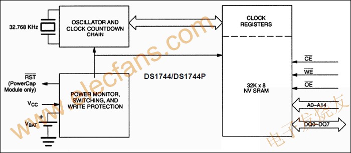
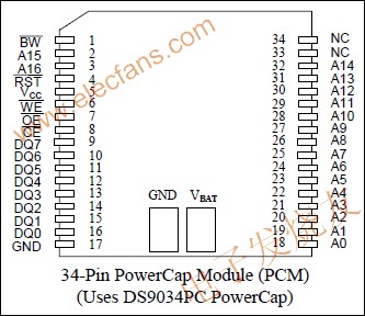
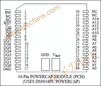
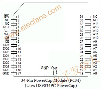
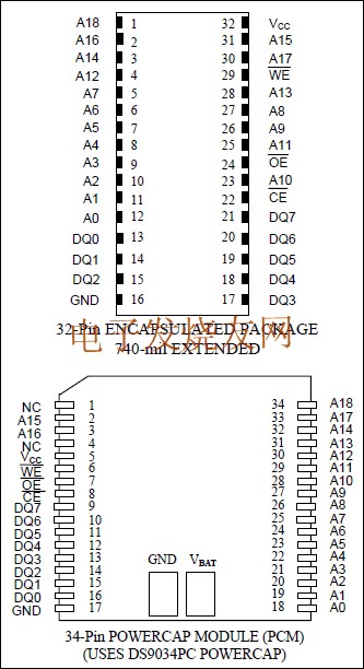
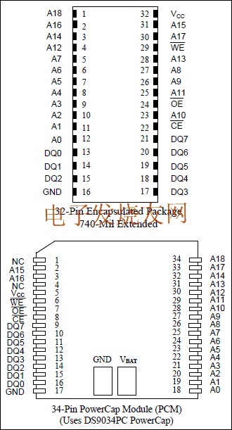
Dallas Semiconductor offers a variety of products that incorporate lithium coin-cell batteries. In some applications, the ability to monitor the battery status is desired to prevent any accidental loss of data when the battery is approaching its useful end-of-life. Battery monitoring is an integral function of the DS1330, DS1345, DS1350 NV SRAM PowerCap Modules, as well as the DS38464 NV SRAM SIMM.
This battery monitoring feature is also featured for sorting in our Parametric Search of memory products at http://para.maxim-ic.com/compare.asp?Fam=Memory&Tree=Memory&HP=Memory.cfm
Installations such as servers or RAID applications that are designed to be 'always-on' rely on the NV SRAM to preserve mission-critical data should a power outage occur. Reliable and expedient system recovery after power restoration is therefore a fundamental necessity, and may warrant some additional overhead in the system architecture.
Figure 1 shows the typical voltage characteristics observed with a lithium coin-cell battery under a fixed 100kΩ load. Dallas has designed a battery monitoring circuit that utilizes the characteristics of lithium batteries under exposure to a known load to determine if the cell remains a viable power source for battery back-up. As this load exposure also requires consumption of some small amount of the battery capacity, the frequency of this exposure was also of concern during the design definition.

Figure 1. Battery discharge plot.
** load selected to accelerate battery discharge for purposes of the graph.
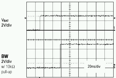
At power-up, and again approximately every 24 hours, an internal 1MΩ test resistor is connected across the battery terminals for one second and the battery voltage is sampled. During that one second period, should the battery voltage (VBAT) fall below a factory-programmed battery warning trip-point (~2.6V), the battery warning output (BW) will be asserted. (see Figure 2) Once asserted, battery testing will be performed approximately every 5 seconds to detect battery removal, and BW will remain active until the weak battery is physically removed and replaced with a fresh cell. Once a fresh cell has been attached, the first passing test result will deassert the BW output and the test interval will return to 24 hours. (see Figure 3) BW is an open-drain output driver.
Battery replacement, in the case of the PowerCap products, should generally be performed when system power is on so that the internal memory content is not corrupted. Normal memory write/read operations are not inhibited while BW is active, but preservation of the data during a power loss cannot be assured. Due to the 5 second test interval, it is required that the battery be removed for more than one test interval, or about 7 seconds, prior to attaching a new battery.
The battery is retested after each power-up, even if BW had been active at power-down.
 Pic/2009-4/200942393926319.gif" border=1>
Figure 2. Power-on battery test fails (VBAT = 2.55V).

Figure 3. Battery Test Passes with Fresh Cell (VBAT = 3.15V).
Based upon the characteristics of the end-of-life voltage profile on the primary batteries used, the occurrence of a valid BW signal should provide the user roughly 500 hours (~3 weeks) advanced notice of an impending battery failure.
Dallas Semiconductor offers a variety of products that incorporate lithium coin-cell batteries. In some applications, the ability to monitor the battery status is desired to prevent any accidental loss of data when the battery is approaching its useful end-of-life. Battery monitoring is an integral function of the DS1330, DS1345, DS1350 NV SRAM PowerCap Modules, as well as the DS38464 NV SRAM SIMM.
This battery monitoring feature is also featured for sorting in our Parametric Search of memory products at http://para.maxim-ic.com/compare.asp?Fam=Memory&Tree=Memory&HP=Memory.cfm
Which Applications Might Require Battery Monitoring?
In field installations requiring very long service lifetimes or those where the environment may introduce some uncertainty in the overall reliability of the battery back-up system, some ability to periodically check the remaining battery capacity is beneficial.Installations such as servers or RAID applications that are designed to be 'always-on' rely on the NV SRAM to preserve mission-critical data should a power outage occur. Reliable and expedient system recovery after power restoration is therefore a fundamental necessity, and may warrant some additional overhead in the system architecture.
How Does the Battery Monitoring Circuit Work?
As outlined in AN505, there are several characteristics of lithium coin-cell batteries that must be understood to accurately predict the service lifetime of the battery. With the flat voltage characteristics of lithium batteries over time, and faced with the environmental variables that an NV SRAM module might be exposed to during the system's life cycle, use of simple open-circuit voltage (OCV) monitoring is not a sufficient gauge of the remaining battery capacity.Figure 1 shows the typical voltage characteristics observed with a lithium coin-cell battery under a fixed 100kΩ load. Dallas has designed a battery monitoring circuit that utilizes the characteristics of lithium batteries under exposure to a known load to determine if the cell remains a viable power source for battery back-up. As this load exposure also requires consumption of some small amount of the battery capacity, the frequency of this exposure was also of concern during the design definition.

Figure 1. Battery discharge plot.
** load selected to accelerate battery discharge for purposes of the graph.
At power-up, and again approximately every 24 hours, an internal 1MΩ test resistor is connected across the battery terminals for one second and the battery voltage is sampled. During that one second period, should the battery voltage (VBAT) fall below a factory-programmed battery warning trip-point (~2.6V), the battery warning output (BW) will be asserted. (see Figure 2) Once asserted, battery testing will be performed approximately every 5 seconds to detect battery removal, and BW will remain active until the weak battery is physically removed and replaced with a fresh cell. Once a fresh cell has been attached, the first passing test result will deassert the BW output and the test interval will return to 24 hours. (see Figure 3) BW is an open-drain output driver.
Battery replacement, in the case of the PowerCap products, should generally be performed when system power is on so that the internal memory content is not corrupted. Normal memory write/read operations are not inhibited while BW is active, but preservation of the data during a power loss cannot be assured. Due to the 5 second test interval, it is required that the battery be removed for more than one test interval, or about 7 seconds, prior to attaching a new battery.
The battery is retested after each power-up, even if BW had been active at power-down.
Figure 2. Power-on battery test fails (VBAT = 2.55V).

Figure 3. Battery Test Passes with Fresh Cell (VBAT = 3.15V).
Based upon the characteristics of the end-of-life voltage profile on the primary batteries used, the occurrence of a valid BW signal should provide the user roughly 500 hours (~3 weeks) advanced notice of an impending battery failure.
 电子发烧友App










评论