Abstract: Integrating analog-to-digital converters (ADCs) provide high resolution analog-to-digital conversions, with good noise rejection. These ADCs are ideal for digitizing low bandwidth signals, and are used in applications such as digital multi-meters and panel meters. They often include LCD or LED drivers and can be used stand alone without a microcontroller host. The following article explains how integrating ADCs work. Discussions include single-, dual- and multi-slope conversions. Also, an in-depth analysis of the integrating architecture will be discussed. Finally a comparisons against other ADC architectures will aid in the understanding and selection of integrating ADCs.
Integrating analog-to-digital converters (ADCs) provide high resolution and can provide good line frequency and noise rejection. Having started with the ubiquitous 7106, these converters have been around for quite some time. The integrating architecture provides a novel yet straightforward approach to converting a low bandwidth analog signal into its digital representation. These type of converters often include built-in drivers for LCD or LED displays and are found in many portable instrument applications, including digital panel meters and digital multi-meters.

Figure 1a and 1b. Single-slope architecture.
One drawback to this approach is that the accuracy is also dependent on the tolerances of the integrator's R and C values. Thus in a production environment, slight differences in each component's value change the conversion result and make measurement repeatability quite difficult to attain. To overcome this sensitivity to the component values, the dual-slope integrating architecture is used.

Figure 2. Dual-slope integration.
The key advantage of this architecture over the single-slope is that the final conversion result is insensitive to errors in the component values. That is, any error introduced by a component value during the integrate cycle will be cancelled out during the de-integrate phase. In equation form:
Vin × TINT = VREF × TDEINT
or
TDEINT = TINT × (VIN / VREF)
From this equation, we see that the de-integrate time is proportional to the ratio of VIN / VREF. A complete block diagram of a dual-slope converter is shown in Figure 3.

Figure 3. Dual-slope converter.
As an example, to obtain 10-bit resolution, you would integrate for 1024 (210) clock cycles, then deintegrate for up to 1024 clock cycles (giving a maximum conversion of 2 × 210 cycles). For more resolution, increase the number of clock cycles. This tradeoff between conversion time and resolution is inherent in this implementation. It is possible to speed up the conversion time for a given resolution with moderate circuit changes. Unfortunately, all improvements shift some of the accuracy to matching, external components, charge injection, etc. In other words, all speed-up techniques have larger error budgets. Even in the simple converter in Figure 1, there are many potential error sources to consider (power-supply rejection [PSR], common-mode rejection [CMR], finite gain, over-voltage concerns, integrator saturation, comparator speed, comparator oscillation, "rollover", dielectric absorption, capacitor leakage current, parasitic capacitance, charge injection, etc).
Instead, we could convert the first 10 most significant bits (one integrate/de-integrate cycle), then amplify the residue by 25, then deintegrate again, then amplify the residue by 25, and then deintegrate for the last time. If the residue is correctly amplified (i.e., charge injection and other errors are small), this technique can be quite powerful in increasing the resolution and reducing the conversion time. Note the actual reading is: (Sum of the first deintegrate time × 210 ) minus (sum of the second deintegrate time × 25 ) plus (sum of the third deintegrate time × 20 ).
The amplifiers must have high common-mode rejection (CMR), power supply rejection (PSR) and high finite gain (so the buffer can adequately drive its resistive load and the integrator its capacitive load). The full-scale integrate current [VIN(max) / RINT] is typically 20-100 microamps. This value is a tradeoff between low power and overcoming the effects of PC board leakage current. Some engineers have tried class B amplifiers for these op amps to save supply current. However, the inevitable crossover distortion must be carefully analyzed, as it can easily be larger than all other errors.
The comparator needs to respond within a fraction of a clock cycle to the fairly small signal. The signal is dependent on the slew rate during deintegrate (I / C = VREF / (RINT × CINT)). As the resolution goes up, this signal can be sub millivolt/microsecond. Unintentional hysteresis must be minimized as this causes "rollover". Rollover is defined as the difference between a near positive full-scale reading and near negative full-scale reading. The parameter is usually specified in the DS data sheet electrical specifications and is tested by simply applying a full-scale positive voltage, then applying a full-scale negative voltage, and then adding the results.
One of the most useful techniques for error reduction is accomplished by shorting the input terminals and taking a measurement. If the ADC design uses up/down counters as accumulators, then the measurement error can be easily subtracted from the input signal (VIN) conversion result. This technique is not always acceptable as it doubles the conversion time if calibration is done prior to every conversion. However, it can correct for many more errors than just the offset error (such as delay of the internal comparator(s), charge injection, etc.).

Figure 4. Model of the integrating capacitor.
The integrating ADC easily converts low-level signals. Since the integrator ramp is set by the value of the integrating resistor, it is fairly easy to match the input signal range to the ADC. Most SARs expect a large signal at the ADC input. Thus for small (i.e., mV) signals, front-end signal conditioning circuitry is required.
The integrating ADC needs more external components than the SAR. A SAR typically needs a couple bypass capacitors. The integrating ADC requires a good integrating and reference capacitors and also a low-drift integrating resistor. In addition, the reference voltage is often a non-standard value (like 100mV or 409.6mV) so a reference voltage divider circuit is often used.
Integrating analog-to-digital converters (ADCs) provide high resolution and can provide good line frequency and noise rejection. Having started with the ubiquitous 7106, these converters have been around for quite some time. The integrating architecture provides a novel yet straightforward approach to converting a low bandwidth analog signal into its digital representation. These type of converters often include built-in drivers for LCD or LED displays and are found in many portable instrument applications, including digital panel meters and digital multi-meters.
Single-Slope ADC Architecture
The simplest form of an integrating ADC uses a single-slope architecture (Figures 1a and 1b). Here, an unknown input voltage is integrated and the value compared against a known reference value. The time it takes for the integrator to trip the comparator is proportional to the unknown voltage (TINT/VIN). In this case, the known reference voltage must be stable and accurate to guarantee the accuracy of the measurement.
Figure 1a and 1b. Single-slope architecture.
One drawback to this approach is that the accuracy is also dependent on the tolerances of the integrator's R and C values. Thus in a production environment, slight differences in each component's value change the conversion result and make measurement repeatability quite difficult to attain. To overcome this sensitivity to the component values, the dual-slope integrating architecture is used.
Dual-Slope ADC Architecture
A dual-slope ADC (DS-ADC) integrates an unknown input voltage (VIN) for a fixed amount of time (TINT), then "de-integrates" (TDEINT) using a known reference voltage (VREF) for a variable amount of time (see Figure 2).
Figure 2. Dual-slope integration.
The key advantage of this architecture over the single-slope is that the final conversion result is insensitive to errors in the component values. That is, any error introduced by a component value during the integrate cycle will be cancelled out during the de-integrate phase. In equation form:
Vin × TINT = VREF × TDEINT
or
TDEINT = TINT × (VIN / VREF)
From this equation, we see that the de-integrate time is proportional to the ratio of VIN / VREF. A complete block diagram of a dual-slope converter is shown in Figure 3.

Figure 3. Dual-slope converter.
As an example, to obtain 10-bit resolution, you would integrate for 1024 (210) clock cycles, then deintegrate for up to 1024 clock cycles (giving a maximum conversion of 2 × 210 cycles). For more resolution, increase the number of clock cycles. This tradeoff between conversion time and resolution is inherent in this implementation. It is possible to speed up the conversion time for a given resolution with moderate circuit changes. Unfortunately, all improvements shift some of the accuracy to matching, external components, charge injection, etc. In other words, all speed-up techniques have larger error budgets. Even in the simple converter in Figure 1, there are many potential error sources to consider (power-supply rejection [PSR], common-mode rejection [CMR], finite gain, over-voltage concerns, integrator saturation, comparator speed, comparator oscillation, "rollover", dielectric absorption, capacitor leakage current, parasitic capacitance, charge injection, etc).
Multi-Slope Integrating ADCs
The normal limit for resolution of the dual-slope architecture is based on the speed of the error comparator (this assumes the DC errors of the system have been minimized by designing for high DC gain, and high PSR and CMR of the buffer, integrator and comparator). For a 20-bit converter (approximately 1 part in a million) and a 1MHz clock, the conversion time would be about 2 seconds. The ramp rate seen by the error comparator is about 2V/106 divided by 1 microsecond. This is about 2 microvolts/microsecond. With such a small slew rate, the error comparator would allow the integrator to go well beyond its trip point by a considerable amount. This overshoot (measured at the integrator output) is called the "residue". This brute force technique is not likely to achieve a 20-bit converter.Instead, we could convert the first 10 most significant bits (one integrate/de-integrate cycle), then amplify the residue by 25, then deintegrate again, then amplify the residue by 25, and then deintegrate for the last time. If the residue is correctly amplified (i.e., charge injection and other errors are small), this technique can be quite powerful in increasing the resolution and reducing the conversion time. Note the actual reading is: (Sum of the first deintegrate time × 210 ) minus (sum of the second deintegrate time × 25 ) plus (sum of the third deintegrate time × 20 ).
In-Depth Architecture Analysis
Auto-Zero
In our previous analysis, we assumed an ideal converter. In actual practice, the circuit will have an offset that drifts over time and temperature. To minimize this affect, dual-slope converters employ an auto-zero phase. During autozeroing, the offset voltage of the buffer op amp the integrator and the comparator is measured and stored on an external capacitor. Thus, the integrate cycle effectively begins with a zeroed offset.Line Rejection
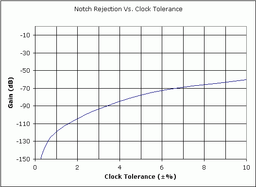
One of the most attractive attributes of the DS-ADC is its rejection of unwanted 50/60Hz signals. If the integrate cycle lasts exactly time T , all frequencies of N × 1/T are completely rejected (theoretically). So for T = 100ms, multiples of 10Hz are rejected. The actual limitation of this rejection is due to the finite swing of the integrator (since we don't want it to saturate) and the inevitable "wobble" of the 50/60Hz frequency itself. Over a long period of time, 50/60Hz can be averaged to get extremely accurate time bases. Over a short time however, it jitters by a few Hertz. This will limit the actual line rejection to about 40-60dB.Error Budget Analysis
DS-ADC's have a several terms in the error budget. This is primarily due to the high accuracy for which they are targeted.The amplifiers must have high common-mode rejection (CMR), power supply rejection (PSR) and high finite gain (so the buffer can adequately drive its resistive load and the integrator its capacitive load). The full-scale integrate current [VIN(max) / RINT] is typically 20-100 microamps. This value is a tradeoff between low power and overcoming the effects of PC board leakage current. Some engineers have tried class B amplifiers for these op amps to save supply current. However, the inevitable crossover distortion must be carefully analyzed, as it can easily be larger than all other errors.
The comparator needs to respond within a fraction of a clock cycle to the fairly small signal. The signal is dependent on the slew rate during deintegrate (I / C = VREF / (RINT × CINT)). As the resolution goes up, this signal can be sub millivolt/microsecond. Unintentional hysteresis must be minimized as this causes "rollover". Rollover is defined as the difference between a near positive full-scale reading and near negative full-scale reading. The parameter is usually specified in the DS data sheet electrical specifications and is tested by simply applying a full-scale positive voltage, then applying a full-scale negative voltage, and then adding the results.
One of the most useful techniques for error reduction is accomplished by shorting the input terminals and taking a measurement. If the ADC design uses up/down counters as accumulators, then the measurement error can be easily subtracted from the input signal (VIN) conversion result. This technique is not always acceptable as it doubles the conversion time if calibration is done prior to every conversion. However, it can correct for many more errors than just the offset error (such as delay of the internal comparator(s), charge injection, etc.).
External Components
A user has to supply the IC with a resistor (for converting the input voltage to a current), an integrator capacitor and an autozero capacitor. Both capacitors needed exceptional DA (dielectric absorption). A model of the integrator capacitor shown in Figure 4 shows the capacitor made up of high value, series R'C' components (caused by the relaxation of the dielectric) in parallel with the main capacitor. These series RC elements cause the capacitor to behave as if it had "memory". For example, suppose a capacitor was charged up to 1.000 Volts for an indefinite time, then shorted out for 10 time constants (SW1 moved to position 1). When the switch is moved to position 3, the capacitor "relaxes" to a voltage other than zero volts due to the "memory" effect. This phenomenon ultimately limits the accuracy, resolution and step response of the converter.
Figure 4. Model of the integrating capacitor.
Versus Other ADC Architectures
We now will look at the integrating ADC versus a SAR and sigma-delta ADC. The flash and pipeline ADC architectures will be ignored since they rarely (if ever) compete against the slower speed integrating architecture.Versus Successive Approximate Register (SAR) ADC
Both the SAR and integrating architectures work well with low bandwidth signals. The SAR ADC has a much wider bandwidth range, as they easily can convert signals at speeds in the low MHz range, while the integrating architecture is limited to about 100 samples/sec. Both architectures have low power consumption. Since SAR ADCs can be shut down between conversions, the effective power consumption is similar to the integrating ADC (to the first order). The biggest difference between the two converters is the common mode rejection and the number of external components required. Because the user sets the integration time, unwanted frequencies, such as 50Hz or 60Hz can effectively be notched out. The SAR ADC does not allow this. In addition, since integration basically is a method of averaging, the integrating ADC typically will have better noise performance. A SAR ADC has code-edge noise and spurious noise that is converted will have a more adverse affect with the SAR ADC than with the integrating ADC.The integrating ADC easily converts low-level signals. Since the integrator ramp is set by the value of the integrating resistor, it is fairly easy to match the input signal range to the ADC. Most SARs expect a large signal at the ADC input. Thus for small (i.e., mV) signals, front-end signal conditioning circuitry is required.
The integrating ADC needs more external components than the SAR. A SAR typically needs a couple bypass capacitors. The integrating ADC requires a good integrating and reference capacitors and also a low-drift integrating resistor. In addition, the reference voltage is often a non-standard value (like 100mV or 409.6mV) so a reference voltage divider circuit is often used.
 电子发烧友App













评论