Abstract: This application note presents a circuit that uses a low-power CMOS comparator to provide an LED visual indication of a low-battery condition. This LBO (low-battery-indicator) is achieved by pulsing the LED at a low frequency and low duty cycle. The circuit accomplishes this without draining excessive battery current that can lead to permanent battery damage and, ultimately, hazardous waste disposal. This circuit also helps conserve battery current in the off cycle by placing the comparator in shutdown. Equations and circuit analysis are included for determining duty cycle and comparator trip points.
The usual method for implementing the low-battery warning featured in most battery-operated equipment is to illuminate an LED. By drawing current, however, the LED exacerbates the low-battery condition. You can greatly reduce the LED's power consumption by operating it at a low frequency and a low duty cycle.
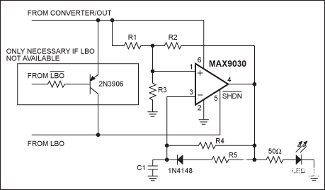
An existing low-battery output (LBO) like that found on DC-DC converters offers a convenient way to light the LED (Figure 1). The MAX9030 is a small, inexpensive comparator with shutdown capability in a 6-pin SC70 package. The device remains in shutdown while the battery voltage is at normal operating levels; it asserts LBO when battery voltage falls below a preset threshold.

Figure 1. Operating this low-battery-warning LED at low frequency and low duty cycle saves power and extends battery life.
Note that LBO (active high) is usable as shown, but an active-low warning (active-low LBO) requires the optional circuitry shown in the box. The MAX9030 then turns on, causing the LED to flash in accordance with the following analysis:
First, keep the duty cycle low:
Batteries can be permanently damaged by frequent low-battery indications or by overdischarge. This is specifically true for nickel metal hydride (NiMh) and Li-ion (Li+) batteries. A fully charged NiMh cell is about 1.4V (unloaded); it supplies a nominal average voltage of 1.2V and can discharge down to about 0.9V. Any further discharge can potentially cause permanent damage to the cell. Also, a fully charged Li+ battery can supply 4.2V (unloaded), and a nominal average voltage of 3.6V. It can discharge down to about 2.5V. Li+ cells must never be discharged below 3V to avoid the possibility of irreversible damage. Once damaged, most of these batteries will end up as hazardous waste and possibly in landfills.
Protecting the environment from excessive, hazardous waste disposal is a global concern. This application circuit helps avoid overdischarging batteries, thus reducing both the number of batteries discarded and their negative impact on the environment.
A similar version of this article appeared in the May 3, 2001 issue of EDN magazine.
The usual method for implementing the low-battery warning featured in most battery-operated equipment is to illuminate an LED. By drawing current, however, the LED exacerbates the low-battery condition. You can greatly reduce the LED's power consumption by operating it at a low frequency and a low duty cycle.
An existing low-battery output (LBO) like that found on DC-DC converters offers a convenient way to light the LED (Figure 1). The MAX9030 is a small, inexpensive comparator with shutdown capability in a 6-pin SC70 package. The device remains in shutdown while the battery voltage is at normal operating levels; it asserts LBO when battery voltage falls below a preset threshold.

Figure 1. Operating this low-battery-warning LED at low frequency and low duty cycle saves power and extends battery life.
Note that LBO (active high) is usable as shown, but an active-low warning (active-low LBO) requires the optional circuitry shown in the box. The MAX9030 then turns on, causing the LED to flash in accordance with the following analysis:
First, keep the duty cycle low:
DC = tON/(tON + tOFF)On-time is derived from the equation for time-varying voltage across a charging capacitor:
V(t) = V(1 - e-t/RC)Off-time is derived from the equation for time-varying voltage across a discharging capacitor:
tON = -R5Cln(1 - VTRIPHI/VOUT)
V(t) = Ve-t/RCThe comparator's high and low trip levels are found using Kirchoff's current laws:
tOFF = -R4Cln(VTRIPLO/VOUT)
VTRIPHI = VOUT[R3(R1 + R2)]/[R3(R1 + R2) + R1R2]The typical VOUT for a comparator is VDD. Assuming a 2.5% duty cycle and assuming that LBO trips the comparator on when battery voltage equals 3V, then the resulting trip levels are 1V for low and 2V for high. The standard component values corresponding to this performance are:
VTRIPLO = VOUT[R3R2]/[R3(R1 + R2) + R1R2]
C1 = 0.1µFThe Figure 1 circuit accommodates any type of LBO output (active high or active low). Supply current drawn by the MAX9030 is typically 35µA when active and only 0.05µA while in shutdown. The circuit's small size, low power consumption, and low cost are ideal for battery-powered systems.
R1 = R2 = R3 = 1MΩ
R4 = 3.6MΩ
R5 = 91kΩ
Batteries can be permanently damaged by frequent low-battery indications or by overdischarge. This is specifically true for nickel metal hydride (NiMh) and Li-ion (Li+) batteries. A fully charged NiMh cell is about 1.4V (unloaded); it supplies a nominal average voltage of 1.2V and can discharge down to about 0.9V. Any further discharge can potentially cause permanent damage to the cell. Also, a fully charged Li+ battery can supply 4.2V (unloaded), and a nominal average voltage of 3.6V. It can discharge down to about 2.5V. Li+ cells must never be discharged below 3V to avoid the possibility of irreversible damage. Once damaged, most of these batteries will end up as hazardous waste and possibly in landfills.
Protecting the environment from excessive, hazardous waste disposal is a global concern. This application circuit helps avoid overdischarging batteries, thus reducing both the number of batteries discarded and their negative impact on the environment.
A similar version of this article appeared in the May 3, 2001 issue of EDN magazine.
 电子发烧友App













评论