Abstract: The MAX5481/MAX5483 data sheet provides a complicated formula for calculating wiper voltage in an effort to be very precise. This application note explains the issues involved in this calculation and breaks the process into smaller steps. It also discusses the proper method for determining the least-significant bit (LSB).
The devices' data sheet (pages 12 and 13) presents the following formulas for calculating the wiper voltage (VW):


Is it any wonder people are turned off? We just want to know the wiper voltage.
We'll start with FSE and ZSE first. The "Electrical Characteristics" table of the data sheet (page 2) indicates that FSE and ZSE are "Full-Scale Error" and "Zero-Scale Error," respectively. Essentially, these parameters describe the residual resistance that may occur at the top and bottom of the potentiometer. This also happens in mechanical potentiometers.
For now, as we design the circuit, forget about FSE and ZSE—they are small and we cannot change them anyway.
We can, thus, simplify Equation 1, which becomes:

Where D is one step as wiper voltage. Therefore, one step is the voltage at the top of the potentiometer minus the bottom voltage divided by 1023. This value is also 1 LSB (least-significant bit).

Figure 1. Illustrating the number of steps versus the number of resistors.
For the sake of illustration, let's say that the bottom of the potentiometer is at 0.2V and the top of the potentiometer is at 2.2V with a 5V supply (Figure 2).
We know that the MAX5482 is 50kΩ end to end. If there is 2V across the potentiometer, there needs to be one-tenth that voltage across R2. R2 is thus 5kΩ. Because we know the voltage and resistance, we can calculate current.
R1 will have 5V minus 2.2V, giving us 2.8V across it. Instead of calculating current, we can look at the ratio (because we can do that in our head). If 2V is equal to 50kΩ, then 2.8V is equal to 70kΩ (1.4 times 50kΩ).
The potentiometer has 2V across it. Dividing by 1023 means that each LSB is 0.001955V.

Figure 2. A typical resistor-divider circuit.
Now back to Equation 2.
Equation 2 simply says that VFSE and VZSE are measured in the voltage of 1 LSB (FSE and ZSE are measured in LSBs). That is, the difference between VH and VL divided by 1023—yes, the data sheet is wrong.
Looking at the data sheet's "Electrical Characteristics" table, the MAX5482's FSE is -0.75 LSB. Thus, -0.75 times 0.001955V (the LSB value above) gives us -0.001466V. VFSE, therefore, is 0.001466V below the nominal voltage of the H terminal's 2V—in other words, 1.9985V VFSE.
And, ZSE is +1.45 LSB (+1.45 times 0.001955V), or 0.002835V above the L terminal's 0.2V. This gives us a total of 0.202835V VZSE.
A mechanical potentiometer data sheet has a typical specification for how close the wiper can get to the ends of the rotation both electrically and in rotational degrees. These specifications are the equivalent of FSE and ZSE in a digital potentiometer.
Yet, we have ignored an error that can be a hundred times greater in this circuit: the ±20% to ±30% end-to-end tolerance of the potentiometer. To learn how to control this error, see application note 4290, "Ratiometric Design Overcomes the 25% Tolerance of a Digital Potentiometer."
Introduction
Sometimes in our effort to be very precise we make things look ridiculously hard. The formulas for calculating the wiper voltage of the MAX5481/MAX5482 digital potentiometers provide a case in point.The devices' data sheet (pages 12 and 13) presents the following formulas for calculating the wiper voltage (VW):


Is it any wonder people are turned off? We just want to know the wiper voltage.
What's This FSE and ZSE Stuff? And Why Do We Care?
The formulas are much less daunting if we break them down into smaller steps.We'll start with FSE and ZSE first. The "Electrical Characteristics" table of the data sheet (page 2) indicates that FSE and ZSE are "Full-Scale Error" and "Zero-Scale Error," respectively. Essentially, these parameters describe the residual resistance that may occur at the top and bottom of the potentiometer. This also happens in mechanical potentiometers.
For now, as we design the circuit, forget about FSE and ZSE—they are small and we cannot change them anyway.
We can, thus, simplify Equation 1, which becomes:

Where D is one step as wiper voltage. Therefore, one step is the voltage at the top of the potentiometer minus the bottom voltage divided by 1023. This value is also 1 LSB (least-significant bit).
Why 1023 Instead of 1024?
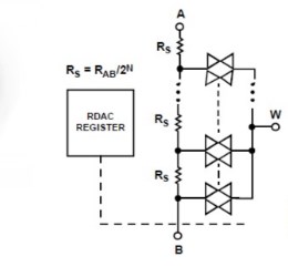
Figure 1 shows the operative concept behind how we end up with 1023 instead of 1024. Note that if there are 8 (0 to 7) steps (switches), there is one less voltage between the steps (i.e., only 7 resistors or LSBs). Zero is the reference that we get for free.
Figure 1. Illustrating the number of steps versus the number of resistors.
For the sake of illustration, let's say that the bottom of the potentiometer is at 0.2V and the top of the potentiometer is at 2.2V with a 5V supply (Figure 2).
We know that the MAX5482 is 50kΩ end to end. If there is 2V across the potentiometer, there needs to be one-tenth that voltage across R2. R2 is thus 5kΩ. Because we know the voltage and resistance, we can calculate current.
R1 will have 5V minus 2.2V, giving us 2.8V across it. Instead of calculating current, we can look at the ratio (because we can do that in our head). If 2V is equal to 50kΩ, then 2.8V is equal to 70kΩ (1.4 times 50kΩ).
The potentiometer has 2V across it. Dividing by 1023 means that each LSB is 0.001955V.

Figure 2. A typical resistor-divider circuit.
Now the Wiper Voltage
If the wiper voltage (VW) is at D step 500, then 500 times 1 LSB is 0.9775V plus the voltage across R2 (0.2V) for a total of 1.1775V.Now back to Equation 2.
Equation 2 simply says that VFSE and VZSE are measured in the voltage of 1 LSB (FSE and ZSE are measured in LSBs). That is, the difference between VH and VL divided by 1023—yes, the data sheet is wrong.
Looking at the data sheet's "Electrical Characteristics" table, the MAX5482's FSE is -0.75 LSB. Thus, -0.75 times 0.001955V (the LSB value above) gives us -0.001466V. VFSE, therefore, is 0.001466V below the nominal voltage of the H terminal's 2V—in other words, 1.9985V VFSE.
And, ZSE is +1.45 LSB (+1.45 times 0.001955V), or 0.002835V above the L terminal's 0.2V. This gives us a total of 0.202835V VZSE.
A mechanical potentiometer data sheet has a typical specification for how close the wiper can get to the ends of the rotation both electrically and in rotational degrees. These specifications are the equivalent of FSE and ZSE in a digital potentiometer.
Conclusion
This application note has explained the relevant calculations required for determining the wiper voltage of a digital potentiometer. By breaking down the process into smaller steps, it has established a much simpler method for these calculations: since the end-point errors (FSE and ZSE) are only 0.28%, Equation 3 is adequate for calculating wiper voltage in most applications.Yet, we have ignored an error that can be a hundred times greater in this circuit: the ±20% to ±30% end-to-end tolerance of the potentiometer. To learn how to control this error, see application note 4290, "Ratiometric Design Overcomes the 25% Tolerance of a Digital Potentiometer."
| Part | Description | Control Interface | Temperature Coefficient (typ, ppm/°C) |
| MAX5482 | 1024-tap, 50kΩ nonvolatile linear-taper digital potentiometer (voltage divider) | 3-wire serial SPI™ | 35 |
| MAX5481 | 1024-tap, 10kΩ nonvolatile linear-taper digital potentiometer (voltage divider) | 3-wire serial SPI | 35 |
 电子发烧友App









评论