Abstract: The DS18B20 and DS18S20 are two very popular 1-Wire digital thermometers. This application note explains the similarities and differences between these two parts, and guides customers in selecting the best part for an application.
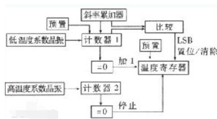
The DS1820 used a dual-oscillator topology to perform a temperature conversion. The resolution of the original DS1820 was only 9 bits. Additional resolution could be achieved by reading two additional register bytes (Count Per °C and Count Remain) and by performing the following calculation. For this calculation, Temp_Read is the value obtained by truncating the 0.5°C bit (bit 0) from the temperature data.

The DS18S20 was designed to be a drop-in replacement for the original DS1820. To work as a replacement, the ADC in the DS18S20 is factory configured to always perform 12-bit conversions. The 12-bit data is then rounded to a 9-bit value and stored in the temperature register. To allow for greater than 9-bit resolution, a value for the Count Remain register is calculated. The Count Per °C register is set by the factory to be 16. Using the Count Remain and the Count Per °C registers and the formula above, up to 12-bit resolution can be obtained with the DS18S20.
The DS18B20 differs from the DS18S20 in an important respect: the designer can select the desired resolution by using the configuration register. This flexibility allows the user to reduce the ADC conversion time and conserve power if higher resolutions are not required. Table 1 shows the temperature conversion time and LSB for each possible resolution setting.
Table 1. DS18B20 Conversion Times and Resolution Settings
The temperature registers of the DS18B20 and DS18S20 are weighted differently. The temperature register in the DS18S20 is weighted to match the DS1820; the DS18B20’s temperature register is formatted to provide 12 bits of resolution. This formatting in the DS18B20 eliminates the need to perform an additional calculation (required by the DS18S20) if greater than 9-bit resolution is required. The default power-up state of the temperature register in both devices is +85°C. The formats for the temperature registers are shown in Tables 2 and 3.
Table 2. DS18S20 Temperature Register Format
Table 3. DS18B20 Temperature Register Format
*S = Sign
The scratchpad memory in these devices (Table 4) also differ slightly. The DS18S20 lacks the configuration register that allows the DS18B20 to change resolution. The DS18S20 does have the two additional registers that are needed if greater than 9 bits of resolution are required.
Table 4. Scratchpad Memory Map Comparison
The 8-bit family code in the ROM code is also different for these two devices. The family code for the DS18B20 is 28h; the DS18S20 retains the same family code as the original DS1820, which is 10h.
Introduction
The DS18B20 and DS18S20 1-Wire devices are both popular and excellent choices for any application requiring digital thermometers. Both devices offer the same resolution and accuracy. The two parts differ only in how the data is presented to the user. This application note describes how the devices work and the differences between them. Applications for each device are recommended.How the Devices Work
The DS18B20 and DS18S20 both use the same base design. Temperature measurements are made using two bandgap-generated voltage sources. One of the voltage sources has a high-temperature coefficient and changes deterministically across temperature. The other voltage source has a low-temperature coefficient and does not change across temperature. An analog-to-digital converter (ADC) converts the difference between these two voltages to a digital value, representing the temperature of the device. The resolution of the temperature conversion can be selected from 9 to 12 bits.Differences Between the Two Devices
We start the discussion with a short digression back to the original DS1820.The DS1820 used a dual-oscillator topology to perform a temperature conversion. The resolution of the original DS1820 was only 9 bits. Additional resolution could be achieved by reading two additional register bytes (Count Per °C and Count Remain) and by performing the following calculation. For this calculation, Temp_Read is the value obtained by truncating the 0.5°C bit (bit 0) from the temperature data.

The DS18S20 was designed to be a drop-in replacement for the original DS1820. To work as a replacement, the ADC in the DS18S20 is factory configured to always perform 12-bit conversions. The 12-bit data is then rounded to a 9-bit value and stored in the temperature register. To allow for greater than 9-bit resolution, a value for the Count Remain register is calculated. The Count Per °C register is set by the factory to be 16. Using the Count Remain and the Count Per °C registers and the formula above, up to 12-bit resolution can be obtained with the DS18S20.
The DS18B20 differs from the DS18S20 in an important respect: the designer can select the desired resolution by using the configuration register. This flexibility allows the user to reduce the ADC conversion time and conserve power if higher resolutions are not required. Table 1 shows the temperature conversion time and LSB for each possible resolution setting.
Table 1. DS18B20 Conversion Times and Resolution Settings
| Resolution | 9 bit | 10 bit | 11 bit | 12 bit |
| Conversion Time (ms) | 93.75 | 187.5 | 375 | 750 |
| LSB (°C) | 0.5 | 0.25 | 0.125 | 0.0625 |
The temperature registers of the DS18B20 and DS18S20 are weighted differently. The temperature register in the DS18S20 is weighted to match the DS1820; the DS18B20’s temperature register is formatted to provide 12 bits of resolution. This formatting in the DS18B20 eliminates the need to perform an additional calculation (required by the DS18S20) if greater than 9-bit resolution is required. The default power-up state of the temperature register in both devices is +85°C. The formats for the temperature registers are shown in Tables 2 and 3.
Table 2. DS18S20 Temperature Register Format
| bit 7 | bit 6 | bit 5 | bit 4 | bit 3 | bit 2 | bit 1 | bit 0 | |
| LSB | 26 | 25 | 24 | 23 | 22 | 21 | 20 | 2-1 |
| MSB | S* | S | S | S | S | S | S | S |
Table 3. DS18B20 Temperature Register Format
| bit 7 | bit 6 | bit 5 | bit 4 | bit 3 | bit 2 | bit 1 | bit 0 | |
| LSB | 23 | 22 | 21 | 20 | 2-1 | 2-2 | 2-3 | 2-4 |
| MSB | S* | S | S | S | S | 26 | 25 | 24 |
The scratchpad memory in these devices (Table 4) also differ slightly. The DS18S20 lacks the configuration register that allows the DS18B20 to change resolution. The DS18S20 does have the two additional registers that are needed if greater than 9 bits of resolution are required.
Table 4. Scratchpad Memory Map Comparison
| DS18S20 | DS18B20 | |
| byte 0 | Temperature LSB (AAh) | Temperature LSB (50h) |
| byte 1 | Temperature MSB (00h) | Temperature MSB (05h) |
| byte 2 | TH Register | TH Register |
| byte 3 | TL Register | TL Register |
| byte 4 | Reserved (FFh) | Configuration Register |
| byte 5 | Reserved (FFh) | Reserved (FFh) |
| byte 6 | Count Remain (0Ch) | Reserved |
| byte 7 | Count Per °C (10h) | Reserved (10h) |
| byte 8 | CRC | CRC |
The 8-bit family code in the ROM code is also different for these two devices. The family code for the DS18B20 is 28h; the DS18S20 retains the same family code as the original DS1820, which is 10h.
Recommended Applications for the DS18S20
The DS18S20 is only recommended for an application that is currently using the original DS1820. Used as a drop-in replacement, the DS18S20 will hopefully save the designer from having to make changes to existing firmware or software. Some code changes may be required, nonetheless, because the DS18S20 has a longer conversion time (750ms) than the DS1820 (500ms).Recommended Applications for the DS18B20
The DS18B20 is recommended for any application that requires 9 to 12 bits of temperature resolution. This device offers much more flexibility and is easier to use than the DS18S20.
1-Wire is a registered trademark of Maxim Integrated Products, Inc.
 电子发烧友App


评论