Abstract: The proper procedure for calibrating sensors using weights is shown with descriptions of typical faults resulting in increased error. Gauge study performance advantages can be gained.
Calibration and temperature compensation of strain-gauge-based weight sensors using the MAX1452 and MAX1455 Precision Sensor Signal Conditioner integrated circuits is becoming increasingly popular. Leading automotive suppliers of safety products are increasingly turning to the use of force sensors in their quest to optimize airbag deployment forces appropriate for the mass of the occupant and severity of the deployment situation.
Although the MAX1452 and MAX1455 incorporate very fine trim and calibration resolution with the 16-bit delta-sigma digital to analog converters (DACs), they cannot compensate for a poor calibration procedure and test setup. Significant points to consider when calibrating a weight sensor are highlighted here along with key test operator functions. A typical dead-weight test system for characterization and initial prototype production will be discussed since that is the type generally employed for characterization and prototype production.
A typical weight sensor characterization requires the use of a dead-weight test stand (also sometimes called a creep-tester) in order to obtain accurate and repeatable sensor loading. Several points must be observed in order to achieve the desired results.
The "No-load" condition is actually not zero, but a positive value resulting from the weight of the cantilevered sensor and the weight of the hanger (hanger includes threaded rod, chain, and weight platter).

Figure 1. Fixture orientation for positive weight application.
The proper fixture orientation for negative weight is shown in Figure 2. The gage marked "A" is now in compression, and the gage marked "B" is now in tension. This produces a negative sensor output signal. The orientation of the sensor does not change. However, the fixtures are now approximately 1 inch longer. Removing the C-brackets, flipping them vertically, and rotating them horizontally produce this fixture orientation.

Figure 2. Fixture orientation for negative weight application.
The "no-load" condition is again not zero, but a negative value resulting from the weight of the cantilevered sensor and the weight of the hanger assembly. This no-load condition is exactly the same value as the positive no-load condition, but reversed in polarity.
There will always be 4 load conditions when cycling from no-load to +load, and no-load to -load. In fact, we shall define the no-load conditions to be +noload and -noload.
An improper fixture arrangement is shown in Figure 3, where the sensor has been flipped and rotated, but the fixtures remain unchanged. At first glance this may appear to apply negative weight, however close inspection of the gages "A" and "B" reveal that they are in the same tension/compression configuration as Figure 1 above and produce the same output signal polarity.

Figure 3. Improper fixture orientation for negative weight application.
Second, the cable weight and tension in the cable will present a load. Although it contributes a minor error to the no-load conditions, it is an error that need not be a concern at all by properly constraining the cable. Proper constraint is achieved when the cable is "hanging on" or supported by "non-active" load side of the sensor. The non-active load side of the sensor is the side where the C-bracket is attached to the upper mount of the test stand.
Figure 4 shows both proper, and improper cable constraint for test. A simple clothespin type clip mounted on the upper shaft allows a quick connect method of cable constraint.

Figure 4. Proper and improper cable constraint, proper is shown at top.

Figure 5. Sensor output variance caused by unequal weights applied in random sequence.

Figure 6. Weight contacting hanger shaft.
When using the dead-weight tester for creep testing, this aspect is again important. Creep testing of a force sensor is intended to measure the amount of semi-permanent offset shift that occurs when a sensor is subjected to a load in a given direction for an extended period of time or over temperature extremes. Creep is shown graphically in Figure 7. A test of creep should include the no load measurement (after proper preconditioning), the continuous monitoring of the test load measurement, and the final no load measurement and subsequent relaxation characteristics.

Figure 7. Creep test measurement requires the accurate application of no load condition.
A related phenomenon is the normal hysteresis of a strain gage sensor assembly when cycled from no load to full load. Although this type of hysteresis typically results in less than 0.01% error, it is a known error factor and should be avoided if possible. This is avoided by using the 3-cycle full-scale load procedure outlined above and applying this procedure whenever a test sequence must be aborted at some intermittent load value and started over.

Figure 8. Application of weights is always increasing or decreasing.
The weights should also be applied in a careful manner so as not to induce large forces on the sensor by inadvertently dropping the weight onto the hanger. A 30LB weight can produce hundreds, even thousands of pounds of force when dropped onto the hanger. Stabilizing the hanging weights before taking a measurement reading is also much simpler when weights are applied carefully.
Calibration and temperature compensation of strain-gauge-based weight sensors using the MAX1452 and MAX1455 Precision Sensor Signal Conditioner integrated circuits is becoming increasingly popular. Leading automotive suppliers of safety products are increasingly turning to the use of force sensors in their quest to optimize airbag deployment forces appropriate for the mass of the occupant and severity of the deployment situation.
Although the MAX1452 and MAX1455 incorporate very fine trim and calibration resolution with the 16-bit delta-sigma digital to analog converters (DACs), they cannot compensate for a poor calibration procedure and test setup. Significant points to consider when calibrating a weight sensor are highlighted here along with key test operator functions. A typical dead-weight test system for characterization and initial prototype production will be discussed since that is the type generally employed for characterization and prototype production.
A typical weight sensor characterization requires the use of a dead-weight test stand (also sometimes called a creep-tester) in order to obtain accurate and repeatable sensor loading. Several points must be observed in order to achieve the desired results.
- Fixture Orientation for Positive and Negative Force Loads on the Test Stand
- Sensor and Cable Orientation
- Torque of the Sensor Mounting Bolts
- Weight Numbering
- Shaft-to-Weight Clearance (When using an automatic weight lift for removing weights from load)
- Pre-conditioning Sensor and Fixtures After Sensor Mounting
- Monotonic Application and Removal of Weights
- Golden Samples and Data Tracking (SPC)
Safety
The first point to be made regards safety. Weights used for weight sensor calibration can be dangerous when not handled properly. Recommended handling practice should include these points:-
Always wear steel-toed shoes or steel shoe covers.
- These are available at any industrial clothing or shoe supply outlet. These weights and fixtures are more than heavy enough to fracture foot bones if dropped accidentally.
-
Always alternate the weight mounting slot orientation every 3-4 weights when stacking.
- Weights stacked in the same orientation can tip and fall off the hanger onto the operator's feet by tipping during the removal of a weight. The weights are designed to be alternately stacked in this way for safety.
-
Always use the leg muscles to lift and lower weights.
- Bending the back to lift a 20LB weight can cause approximately 720 IN-LB of torque to be exerted by the lower back bones and muscle in addition to the compressive weight load itself on the same joints.
-
Always secure fixtures and rods with the maximum allowable thread engagement.
- Engaging threaded joints only one or two threads (or turns) provides insufficient screw thread engagement and may strip away under load causing the weights and fixtures to fall.
Fixture Orientation
The proper fixture orientation for a typical doubly-constrained S-bend weight sensor under positive weight is shown in Figure 1. The gage marked "A" is load in tension, and the gage marked "B" is in compression.The "No-load" condition is actually not zero, but a positive value resulting from the weight of the cantilevered sensor and the weight of the hanger (hanger includes threaded rod, chain, and weight platter).

Figure 1. Fixture orientation for positive weight application.
The proper fixture orientation for negative weight is shown in Figure 2. The gage marked "A" is now in compression, and the gage marked "B" is now in tension. This produces a negative sensor output signal. The orientation of the sensor does not change. However, the fixtures are now approximately 1 inch longer. Removing the C-brackets, flipping them vertically, and rotating them horizontally produce this fixture orientation.

Figure 2. Fixture orientation for negative weight application.
The "no-load" condition is again not zero, but a negative value resulting from the weight of the cantilevered sensor and the weight of the hanger assembly. This no-load condition is exactly the same value as the positive no-load condition, but reversed in polarity.
There will always be 4 load conditions when cycling from no-load to +load, and no-load to -load. In fact, we shall define the no-load conditions to be +noload and -noload.
An improper fixture arrangement is shown in Figure 3, where the sensor has been flipped and rotated, but the fixtures remain unchanged. At first glance this may appear to apply negative weight, however close inspection of the gages "A" and "B" reveal that they are in the same tension/compression configuration as Figure 1 above and produce the same output signal polarity.

Figure 3. Improper fixture orientation for negative weight application.
Sensor and Cable Orientation
Keeping the sensor in the same orientation for all tests is important for a couple of reasons. First, the sensor body is a cantilevered load. Although the doubly constrained S-bend loading tends to cancel common mode cantilever effects, it is best practice not to rely on a sensor property for cancellation when simple attention to fixture orientation eliminates the issue altogether.Second, the cable weight and tension in the cable will present a load. Although it contributes a minor error to the no-load conditions, it is an error that need not be a concern at all by properly constraining the cable. Proper constraint is achieved when the cable is "hanging on" or supported by "non-active" load side of the sensor. The non-active load side of the sensor is the side where the C-bracket is attached to the upper mount of the test stand.
Figure 4 shows both proper, and improper cable constraint for test. A simple clothespin type clip mounted on the upper shaft allows a quick connect method of cable constraint.

Figure 4. Proper and improper cable constraint, proper is shown at top.
Weight Numbering
All weights are not created equal. Generally dead weights are traceable to NIST primary standards via secondary, or terserary traceable standards by qualified calibration laboratories. Sometimes inexpensive weights are not traceable at all and can vary in weight by as much as 10% from each other. In any case, the weights should be marked with a unique identification number on the edge and top surfaces such that they can be applied and removed in a repetitive sequence. The non-equal weights will result in a slight non-monotonic application of force to the sensor. When such weights are applied in any random order, the result is a sensor output curve that is non-repeatable with respect to linearity. This is shown in an exaggerated sense in Figure 5. As stated before, although this random variance error is minor, it does not have to be concerned about at all if the weights are applied in the same sequence each time.
Figure 5. Sensor output variance caused by unequal weights applied in random sequence.
Shaft-to-Weight Clearance
When using an automatic weight lift mechanism, careful control of the shaft position within the weight slots is required. Figure 6 shows weight with a slot for loading and unloading on the hanger. When the weight lift is raised to remove the weights from the hanger, any contact between the threaded-rod shaft and the weight slot will result in a hysteresis effect and/or a misleading measurement of the no-load condition.
Figure 6. Weight contacting hanger shaft.
When using the dead-weight tester for creep testing, this aspect is again important. Creep testing of a force sensor is intended to measure the amount of semi-permanent offset shift that occurs when a sensor is subjected to a load in a given direction for an extended period of time or over temperature extremes. Creep is shown graphically in Figure 7. A test of creep should include the no load measurement (after proper preconditioning), the continuous monitoring of the test load measurement, and the final no load measurement and subsequent relaxation characteristics.

Figure 7. Creep test measurement requires the accurate application of no load condition.
Pre-Conditioning Sensor and Fixtures After Mounting
The sensor and fixture assembly must be repeatedly loaded to full scale and back to no load three times after each sensor mounting, torqueing of fixtures bolts, and after aborted runs. The reason is that there is a small frictional component around each fixture to sensor contact surface that can slightly alter the stress profile about the sensor mounting location. When loads are applied, this friction region slips to a point most stable between a no load, and full load condition. The sensor itself will also exhibit stress relief in the protective polymer coatings covering the gages themselves. Cycling a load three times relieves these stresses and establishes a true no load zero output from the sensor to begin a test run from.A related phenomenon is the normal hysteresis of a strain gage sensor assembly when cycled from no load to full load. Although this type of hysteresis typically results in less than 0.01% error, it is a known error factor and should be avoided if possible. This is avoided by using the 3-cycle full-scale load procedure outlined above and applying this procedure whenever a test sequence must be aborted at some intermittent load value and started over.
Monotonic Application and Removal of Weights
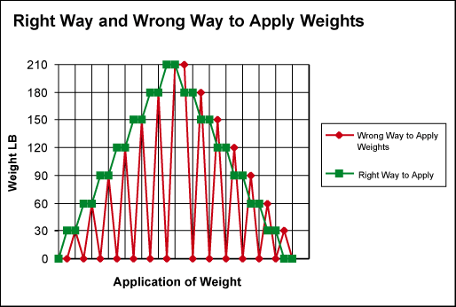
During a test sequence, weights should be applied in a continuously increasing manner for loading, and removed in a continuously decreasing manner during unloading. This avoids disturbing the hysteresis loop established by the 3-cycle preconditioning outlined above. This sequence is shown in Figure 8.
Figure 8. Application of weights is always increasing or decreasing.
The weights should also be applied in a careful manner so as not to induce large forces on the sensor by inadvertently dropping the weight onto the hanger. A 30LB weight can produce hundreds, even thousands of pounds of force when dropped onto the hanger. Stabilizing the hanging weights before taking a measurement reading is also much simpler when weights are applied carefully.
Golden Samples and Data Tracking (SPC)
The Test Group or Quality Assurance group should maintain several "Golden Sample" sensors (with or without electronics) for confirmation or validation of the test stands readiness for use. These samples should be measured periodically on the test stand and the data recorded in a log. Release of the equipment for use should be granted only after the Golden Samples are run and the data results deemed acceptable. This log becomes the primary traceable record of equipment capability throughout the life of the tester. The Golden Samples should be run whenever one of the following conditions applies:- The test stand is moved.
- The test stand or fixtures are modified and/or replaced.
- Weights are replaced or altered.
- Prior to testing any sensors intended for customer use, design or process verification testing.
- Tester-to-Tester Reproducibility checks
 电子发烧友App


评论