Abstract: A PIN photodiode, four low-noise op amps and a comparator are used to detect individual photons of gamma radiation. The schematic, design considerations and component selection are discussed.
The circuit of Figure 1 includes a PIN photodiode that detects individual photons of gamma radiation. When a photon strikes a depletion region created by reverse bias on the photodiode, it produces a small amount of charge in proportion to the photon's energy. The resulting signal is then amplified and filtered by four amplifiers and a final comparator distinguishes between the signal and noise. The comparator output pulses high each time a gamma photon with sufficient energy strikes the photodiode.

Figure 1. When a single gamma photon with sufficient energy strikes the PIN Photodiode in this circuit, the output of the comparator pulses high.
Small signal levels make this design an interesting challenge. It requires very low-noise circuitry, both because the amount of charge generated by individual gamma photons is extremely small, and because lowering the overall noise level allows the circuit to detect lower-energy gamma photons. Special attention must paid to the first stage, which is the most noise-critical.
Large-area detectors tend to have higher capacitance, which increases the noise gain of the circuit. Similarly, a higher bias voltage means higher leakage current. Leakage current also generates noise. The Figure 1 circuit includes a PIN photodiode from Fairchild (QSE773). Though available and inexpensive, it is probably not optimal. Certain PIN photodiodes from Hamamatsu can work nicely in this application, however. Choosing a detector with 25pF to 50pF of capacitance under reverse bias provides a fair compromise between sensitivity and noise.
Important considerations for the first-stage op amp include input-voltage noise, input-current noise, and input capacitance. Input-current noise is directly in the signal path, so the op amp should minimize that parameter. JFET- or CMOS-input op amps are a must. Also (if possible) the op amp's input capacitance should be small compared to the PIN photodiode's capacitance.
If you use a high-quality PIN photodiode and an op amp with low current noise, and pay careful attention to design, the limiting factor for noise should be the first-stage op amp's input-voltage noise multiplied by the total capacitance at the op amp's inverting node. That capacitance includes the PIN photodiode capacitance, the op-amp input capacitance, and the feedback capacitance C1. Thus, to minimize circuit noise, minimize the op amp's input-voltage noise.
The op amp shown in this circuit (MAX4477) enables this design. It has negligible input-current noise and exceptionally low input-voltage noise: 3.5 to 4.5nV/RtHz at the critical frequencies of 10kHz to 200kHz. Its input capacitance is a respectably low 10pF.
R1 and R2 contribute equally to noise because they are directly in the signal path. Resistor current noise is inversely proportional to the square root of its resistance, so use as large a resistance value as the circuit can tolerate. Keep in mind, though, that leakage current from the PIN diode and first-stage op amp place a practical limit on how large the resistance can be. MAX4477 leakage current is only 150pA maximum, so R2 could be much larger than the 10MW shown. R1 can also be substantially larger when operating with a high-quality PIN photodiode.
C1 affects the circuit gain, and smaller values benefit both noise and gain. Use a capacitor with low temperature coefficient to avoid gain changes with temperature. This capacitance value also affects the requirement for gain bandwidth product (GBWP) in the op amp. Smaller capacitance values require a higher GBWP.
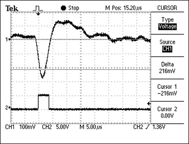
You can test the circuit with a cheap smoke detector. The ionizing types of smoke detectors use americium 241, which emits a 60keV gamma photon. (The more expensive photoelectric smoke detectors do not contain americium.) A 60keV gamma is close to the circuit's noise floor, but should be detectable. A graph (Figure 2) shows the result of a typical gamma strike. The top waveform is from Test Point 1, and the bottom waveform is the comparator output.

Figure 2. These waveforms from the Figure 1 circuit show the signal at Test Point 1 (top trace) when a gamma photon strikes the PIN photodiode, and the resulting comparator output (bottom trace).
A possible improvement would be to replace C1 with a digitally-trimmable capacitor such as the MAX1474, which provides the circuit with digitally-programmable gain. Similarly, replacing the mechanical pot with a digital pot such as the MAX5403 allows digital adjustment of the comparator threshold. Finally, driving the comparator non-inverting input with a reference instead of the 5V supply improves the comparator-threshold stability.
The circuit of Figure 1 includes a PIN photodiode that detects individual photons of gamma radiation. When a photon strikes a depletion region created by reverse bias on the photodiode, it produces a small amount of charge in proportion to the photon's energy. The resulting signal is then amplified and filtered by four amplifiers and a final comparator distinguishes between the signal and noise. The comparator output pulses high each time a gamma photon with sufficient energy strikes the photodiode.

Figure 1. When a single gamma photon with sufficient energy strikes the PIN Photodiode in this circuit, the output of the comparator pulses high.
Small signal levels make this design an interesting challenge. It requires very low-noise circuitry, both because the amount of charge generated by individual gamma photons is extremely small, and because lowering the overall noise level allows the circuit to detect lower-energy gamma photons. Special attention must paid to the first stage, which is the most noise-critical.
Component Considerations
The most critical component is the PIN photodiode, whose selection often involves conflicting considerations. Detector sensitivity, for example (the number of photons detected for a given radiation field) depends on the size of the depletion region, which in turn depends on the area of the diode and the amount of reverse bias applied to it. To maximize sensitivity, therefore, you should choose a large-area detector with high reverse bias. But, both of those conditions add noise.Large-area detectors tend to have higher capacitance, which increases the noise gain of the circuit. Similarly, a higher bias voltage means higher leakage current. Leakage current also generates noise. The Figure 1 circuit includes a PIN photodiode from Fairchild (QSE773). Though available and inexpensive, it is probably not optimal. Certain PIN photodiodes from Hamamatsu can work nicely in this application, however. Choosing a detector with 25pF to 50pF of capacitance under reverse bias provides a fair compromise between sensitivity and noise.
Important considerations for the first-stage op amp include input-voltage noise, input-current noise, and input capacitance. Input-current noise is directly in the signal path, so the op amp should minimize that parameter. JFET- or CMOS-input op amps are a must. Also (if possible) the op amp's input capacitance should be small compared to the PIN photodiode's capacitance.
If you use a high-quality PIN photodiode and an op amp with low current noise, and pay careful attention to design, the limiting factor for noise should be the first-stage op amp's input-voltage noise multiplied by the total capacitance at the op amp's inverting node. That capacitance includes the PIN photodiode capacitance, the op-amp input capacitance, and the feedback capacitance C1. Thus, to minimize circuit noise, minimize the op amp's input-voltage noise.
The op amp shown in this circuit (MAX4477) enables this design. It has negligible input-current noise and exceptionally low input-voltage noise: 3.5 to 4.5nV/RtHz at the critical frequencies of 10kHz to 200kHz. Its input capacitance is a respectably low 10pF.
R1 and R2 contribute equally to noise because they are directly in the signal path. Resistor current noise is inversely proportional to the square root of its resistance, so use as large a resistance value as the circuit can tolerate. Keep in mind, though, that leakage current from the PIN diode and first-stage op amp place a practical limit on how large the resistance can be. MAX4477 leakage current is only 150pA maximum, so R2 could be much larger than the 10MW shown. R1 can also be substantially larger when operating with a high-quality PIN photodiode.
C1 affects the circuit gain, and smaller values benefit both noise and gain. Use a capacitor with low temperature coefficient to avoid gain changes with temperature. This capacitance value also affects the requirement for gain bandwidth product (GBWP) in the op amp. Smaller capacitance values require a higher GBWP.
Finishing Touches
To insure that the circuit measures gamma radiation and not light, cover the PIN photodiode with an opaque material. To block radiated emission from power lines, computer monitors, etc., be sure to shield the circuit with a grounded enclosure.You can test the circuit with a cheap smoke detector. The ionizing types of smoke detectors use americium 241, which emits a 60keV gamma photon. (The more expensive photoelectric smoke detectors do not contain americium.) A 60keV gamma is close to the circuit's noise floor, but should be detectable. A graph (Figure 2) shows the result of a typical gamma strike. The top waveform is from Test Point 1, and the bottom waveform is the comparator output.

Figure 2. These waveforms from the Figure 1 circuit show the signal at Test Point 1 (top trace) when a gamma photon strikes the PIN photodiode, and the resulting comparator output (bottom trace).
A possible improvement would be to replace C1 with a digitally-trimmable capacitor such as the MAX1474, which provides the circuit with digitally-programmable gain. Similarly, replacing the mechanical pot with a digital pot such as the MAX5403 allows digital adjustment of the comparator threshold. Finally, driving the comparator non-inverting input with a reference instead of the 5V supply improves the comparator-threshold stability.
 电子发烧友App






评论