For many automobiles, the same set of LEDs illuminates both tail lights and brake lights. The LEDs must therefore operate at two different brightness levels: full brightness for braking, and 10% to 25% of that brightness (dimmed) for the tail lights. Dimming is best achieved with pulse-width modulation (PWM), which maintains the LED's color spectrum over its brightness range. Moreover, an LED-driver IC that generates an internal 200Hz ramp signal can simplify the driver design by eliminating the need for an external PWM signal. This application note uses the MAX16804 high-brightness LED (HB LED) driver. The MAX16804 integrates a dual-mode DIM pin and on-board 200Hz ramp generator, eliminates the need for an external PWM signal, and simplifies the driver design.
A similar article appeared in the May, 2009 edition of EDN China.
The functions of tail light (dimmed LEDs) and brake light (full brightness) are controlled by the LED driver's TAIL and STOP inputs. When the TAIL voltage is high, the tail-light LEDs are driven at 10% to 25% of full brightness. When STOP is high (while braking), the LEDs are driven at full brightness regardless of the TAIL input.
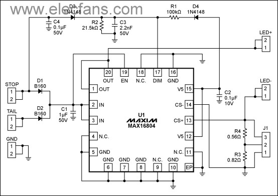
Figure 1. Circuit schematic of evaluation board for the MAX16804 high-brightness LED driver.
The supply inputs for STOP and TAIL connect to the IN pins through diodes D1 and D2. The IC can be powered through either input, with no effect on the other input. D1 and D2 also provide protection against any reverse voltage spike that may be present on the automotive supply bus. Capacitors C4 and C3 protect the DIM pin by bypassing any noise spike that may be present on the STOP line.
Figure 2. Photo of the MAX16804 evaluation board (schematic shown in Figure 1).
Use Equation 2 to choose the R1 and R2 values that apply this voltage at DIM:
To set a different current level, use the following equation to calculate a value for the current-sense resistor (R3 or R4).
Note: the MAX16804 evaluation board can dissipate the IC's rated power continuously at 25?C ambient, but at higher ambient temperatures you should reduce its power dissipation to prevent the IC from entering thermal shutdown. A parts list for this board, with views of the pc layout and component placement is available for download (PDF).
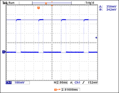
Figure 3. 350mA LED current in TAIL mode, measured using a 1Ω current-sense resistor, 12V VIN, and 9.3V LED forward voltage. For 20% brightness in TAIL mode, the LED current is pulsed at 200Hz, with a 20% duty cycle and 350mA amplitude.
During TAIL mode (Figures 3 and 5) the 200Hz, 20% duty cycle reduces brightness by allowing LED current to flow only 1/5 of the time. The LED current amplitude is precisely regulated (to the set level) in both STOP and TAIL modes, and its rise and fall times are wave-shaped to reduce EMI.
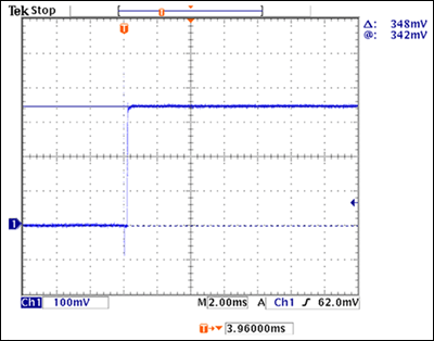
Figure 4. 350mA LED current in STOP mode, measured using a 1Ω current-sense resistor, 12V VIN, and 9.3V LED forward voltage. Full brightness in STOP mode requires a continuous 350mA of LED current.
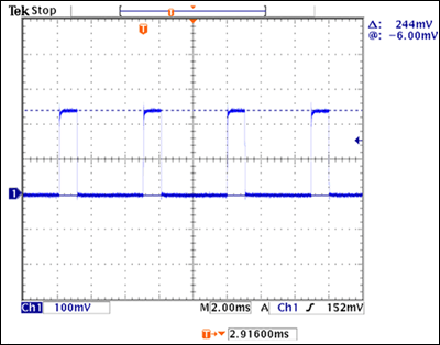
Figure 5. 240mA LED current in TAIL mode, measured using a 1Ω current-sense resistor, 12V VIN, and 9.1V LED forward voltage. For 20% brightness in TAIL mode, the LED current is pulsed at 200Hz, with a 20% duty cycle and 240mA amplitude.
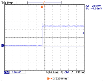
Figure 6. 240mA LED current in STOP mode, measured using a 1Ω current-sense resistor, 12V VIN, and 9.3V LED forward voltage. Full brightness in STOP mode requires a continuous 240mA of LED current.
A similar article appeared in the May, 2009 edition of EDN China.
The functions of tail light (dimmed LEDs) and brake light (full brightness) are controlled by the LED driver's TAIL and STOP inputs. When the TAIL voltage is high, the tail-light LEDs are driven at 10% to 25% of full brightness. When STOP is high (while braking), the LEDs are driven at full brightness regardless of the TAIL input.
Tail-light driver specifications
- Input supply voltage (between STOP or TAIL and ground) is a nominal 6V to 16V, and up to 45V during a load dump.
- Output voltage (VLED) is as high as (VIN - 1.4V).
- Output current (LED current) while braking is 350mA, 240mA, or 140mA, depending on J1 setting.
- PWM duty cycle of LED current for tail lights is 20%.
Inputs
- STOP: applying an input supply voltage of 6V to 16V between STOP(+) and GND(-) drives the LEDs with a continuous 350mA, 240mA, or 140mA, depending on the J1 setting.
- TAIL: applying an input supply voltage of 6V to 16V between TAIL(+) and GND(-) drives the LEDs with 350mA, 240mA, or 140mA at 10% duty cycle, depending on the J1 setting.
Outputs
- LED+: Connect to LED anode.
- LED-: Connect to LED cathode.
Circuit description
The LED-driver functions for automotive rear lighting (STOP and TAIL) can easily be implemented with a linear LED-driver IC requiring a minimum of external components, such as the device shown (MAX16804). See the schematic for the driver circuit (Figure 1) and its pc board (Figure 2). Maximum current through the LEDs is set by R3 or R4 according to the J1 connections, and brightness is controlled by PWM, implemented within the IC. The IC delivers a 200Hz drive signal to the LEDs, with duty cycle adjusted according to the voltage level at DIM. A DIM voltage of 0.78V, for example, produces a 20% tail-light brightness.
Figure 1. Circuit schematic of evaluation board for the MAX16804 high-brightness LED driver.
The supply inputs for STOP and TAIL connect to the IN pins through diodes D1 and D2. The IC can be powered through either input, with no effect on the other input. D1 and D2 also provide protection against any reverse voltage spike that may be present on the automotive supply bus. Capacitors C4 and C3 protect the DIM pin by bypassing any noise spike that may be present on the STOP line.
Figure 2. Photo of the MAX16804 evaluation board (schematic shown in Figure 1).
Tail-mode operation
A supply voltage at the TAIL input only applies a constant 0.78V (generated from the +5V regulator output) to DIM, which in turn causes the LEDs to be driven with a 20% duty cycle. This PWM duty cycle during TAIL mode is independent of the voltage level at TAIL. Resistor divider R1/R2 sets the voltage level at DIM during TAIL mode. For duty cycles other than 20%, use the following equation to determine the corresponding voltage level at DIM (VDIM):where D is the desired duty cycle in percent.
Use Equation 2 to choose the R1 and R2 values that apply this voltage at DIM:
where 0.6V is the forward drop of diode D2, 5V is the regulator output, and VDIM is the voltage you must apply at DIM pin to get the desired PWM duty cycle. To avoid a considerable change in DIM voltage due to the input bias current at DIM, choose an R2 value near 20kΩ.
STOP-mode operation
The voltage at DIM must be above 3.1V to obtain a 100% duty cycle. When the STOP input is applied, DIM is driven sufficiently high via D3 to guarantee the 100% duty cycle. As a result, the LEDs are driven with a continuous current of 350mA regardless of the voltage applied at TAIL.LED current setting
An evaluation board for the MAX16804 lets you select one of three current levels (140mA, 240mA, or 350mA) by setting the jumper J1:| J2 jumper connection | 1 and 2 | 2 and 3 | Open |
| LED current | 350mA | 240mA | 140mA |
To set a different current level, use the following equation to calculate a value for the current-sense resistor (R3 or R4).
where 0.198V is the regulated current-sense voltage, and IOUT is the desired LED current in amperes.
Power dissipation
The device shown (MAX16804) can dissipate up to 2.758W of power. In this application, it dissipates maximum power during STOP mode. The following equation lets you calculate this maximum power dissipation.where VIN is the supply voltage at the IN pins, VLED is the forward voltage of the LED string, and 350mA is the maximum LED current that can be set with jumper J1. Most of this power exits the device through the exposed pad. You should therefore solder the exposed pad to a pad of equal size on the board, and use an array of vias to connect that pad to a copper ground plane of sufficient area.
Note: the MAX16804 evaluation board can dissipate the IC's rated power continuously at 25?C ambient, but at higher ambient temperatures you should reduce its power dissipation to prevent the IC from entering thermal shutdown. A parts list for this board, with views of the pc layout and component placement is available for download (PDF).
Power-up procedure
- Connect LED+ to the anode and LED- to the cathode of the LED or LED string.
- To enable a 350mA LED current, connect J1 pins 1 and 2.
- For the STOP operating mode, connect a supply voltage between STOP(+) and GND(-). This voltage should be 6V minimum, and at least 1.4V greater than the LED forward voltage.
- For the TAIL operating mode, remove the supply voltage at STOP and connect it between TAIL(+) and GND(-).
Test results
Figures 3–6 show the LED current waveform in STOP and TAIL modes, for LED currents of 350 mA and 240 mA. During STOP mode, where you need the full LED brightness (Figures 4 and 6), LED current rises to the set value (350mA or 240mA) as soon as you apply power between the STOP input and ground. The LED current is on continuously, and does not overshoot from the set value.
Figure 3. 350mA LED current in TAIL mode, measured using a 1Ω current-sense resistor, 12V VIN, and 9.3V LED forward voltage. For 20% brightness in TAIL mode, the LED current is pulsed at 200Hz, with a 20% duty cycle and 350mA amplitude.
During TAIL mode (Figures 3 and 5) the 200Hz, 20% duty cycle reduces brightness by allowing LED current to flow only 1/5 of the time. The LED current amplitude is precisely regulated (to the set level) in both STOP and TAIL modes, and its rise and fall times are wave-shaped to reduce EMI.

Figure 4. 350mA LED current in STOP mode, measured using a 1Ω current-sense resistor, 12V VIN, and 9.3V LED forward voltage. Full brightness in STOP mode requires a continuous 350mA of LED current.

Figure 5. 240mA LED current in TAIL mode, measured using a 1Ω current-sense resistor, 12V VIN, and 9.1V LED forward voltage. For 20% brightness in TAIL mode, the LED current is pulsed at 200Hz, with a 20% duty cycle and 240mA amplitude.

Figure 6. 240mA LED current in STOP mode, measured using a 1Ω current-sense resistor, 12V VIN, and 9.3V LED forward voltage. Full brightness in STOP mode requires a continuous 240mA of LED current.
 电子发烧友App






评论