Abstract: USB powered devices require a regulated supply. Unfortunately, the USB bus voltage can vary from 4V to 9V. Configuring the MAX668 boost controller into step-up/step-down topology can generate a current-limited regulated supply.
Universal Serial Bus (USB) is a popular way to connect PCs and consumer devices. It is simple and inexpensive and can connect multiple external peripherals simultaneously. As mobile devices add more functionality such as text messaging, web surfing, information storage and music playing, the need to communicate with a PC is increasing. Many of the mobile devices today offer a USB interface native in the device. The sole purpose is to provide a connection for data communication. The device may be self powered (e.g., through a wall adapter) or draw the power from the USB bus.
The mobile devices are typically expected to connect to a powered USB hub. A USB device can have its own power source (e.g. batteries or a wall plug) or draw the power from the USB bus. A powered USB host can provide up to 500mA current. Using the power supplied by USB can be tricky because the voltage to a USB powered device may be as low as 4.35V, when cable and connector drops are considered, or as high as 5.5V. If the device is to operate with a voltage adapter for a source it may see input voltages as high as 9V. In order to accommodate these various scenarios, a step-up/step-down DC-DC topology works well. The input and output specifications for a controller/converter are summarized in Table 1.
Table 1. Power Supply Requirements for USB Compatible Portable Device

Figure 1. SEPIC power supply for USB compatible device.
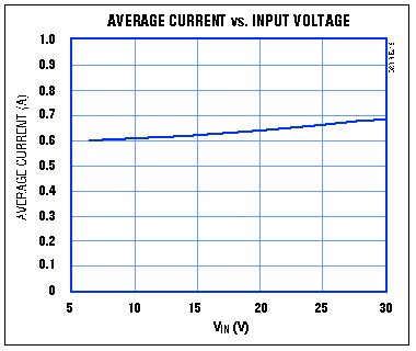
The current limit resistor R4 (Figure 1) is used to limit the input current to a maximum of 500mA as specified in Table 1. The input current limit also ensures short-circuit protection ensuring USB compliance even under output fault conditions. When the output exceeds the input current limit the output voltage will reduce and restrict the input current to 500mA as shown in Figure 2. Note the extra inductor required in this topology as compared to a regular boost topology.

Figure 2. Input current limiting using MAX668 SEPIC.
The use of a coupled inductor (two inductors wound on the same core) such as the Coiltronics CTX10-3 (Figure 1) reduces the leakage inductance. This makes it possible to achieve efficiencies of up to 85% in practice. Efficiency for this SEPIC converter is shown in Figure 3.

Figure 3. Efficiency of the MAX668 SEPIC.
Universal Serial Bus (USB) is a popular way to connect PCs and consumer devices. It is simple and inexpensive and can connect multiple external peripherals simultaneously. As mobile devices add more functionality such as text messaging, web surfing, information storage and music playing, the need to communicate with a PC is increasing. Many of the mobile devices today offer a USB interface native in the device. The sole purpose is to provide a connection for data communication. The device may be self powered (e.g., through a wall adapter) or draw the power from the USB bus.
The mobile devices are typically expected to connect to a powered USB hub. A USB device can have its own power source (e.g. batteries or a wall plug) or draw the power from the USB bus. A powered USB host can provide up to 500mA current. Using the power supplied by USB can be tricky because the voltage to a USB powered device may be as low as 4.35V, when cable and connector drops are considered, or as high as 5.5V. If the device is to operate with a voltage adapter for a source it may see input voltages as high as 9V. In order to accommodate these various scenarios, a step-up/step-down DC-DC topology works well. The input and output specifications for a controller/converter are summarized in Table 1.
Table 1. Power Supply Requirements for USB Compatible Portable Device
| Parameter | Requirement |
| Input Voltage VIN | 4V to 9V |
| Input Current IIN | 500mA (±5%) max. |
| Output Power POUT | 2.4W typical |
| Output Voltage VOUT | 6V (±5%) typical |
| Output Load Current IOUT | 400mA max. |
| Regulation | Min. VOUT =5.5V at IOUT = 200mA |
SEPIC to 6V with Input Current Limiting
This step-up/step-down supply is used to power a Li+ battery charger. Since the charger itself will have a drop in voltage across it, the output voltage was set to 6V. The single-ended primary inductance converter shown in Figure 1 is ideal for this application. This buck-boost topology is needed since the input voltage can vary from values below the output voltage to values greater than the output voltage (Table 1). The MAX668 boost controller is adapted to SEPIC topology (Figure 1).
Figure 1. SEPIC power supply for USB compatible device.
The current limit resistor R4 (Figure 1) is used to limit the input current to a maximum of 500mA as specified in Table 1. The input current limit also ensures short-circuit protection ensuring USB compliance even under output fault conditions. When the output exceeds the input current limit the output voltage will reduce and restrict the input current to 500mA as shown in Figure 2. Note the extra inductor required in this topology as compared to a regular boost topology.

Figure 2. Input current limiting using MAX668 SEPIC.
The use of a coupled inductor (two inductors wound on the same core) such as the Coiltronics CTX10-3 (Figure 1) reduces the leakage inductance. This makes it possible to achieve efficiencies of up to 85% in practice. Efficiency for this SEPIC converter is shown in Figure 3.

Figure 3. Efficiency of the MAX668 SEPIC.
 电子发烧友App







评论