Abstract: This application note discusses hardware design techniques to build monocolour and bicolour graphic message boards using the MAX6952 and MAX6953 SPI™ and I²C 5x7 matrix LED display drivers.
This application note is one of two application notes that discuss the software and processor interface issues in the application of the MAX6952 and MAX6953 LED drivers to build an LED matrix graphic panel for message boards and animated graphic displays. This note covers the electrical aspects of the panel design; the other note, Software Control of the MAX6952 and MAX6953 LED Drivers in Graphic Applications, covers the software aspects of the panel design.
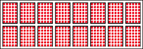
The MAX6952 and MAX6953 are 4-digit cathode-row 5x7 matrix LED display drivers that are controlled through a high-speed SPI (MAX6952) or I²C (MAX6953) serial interface. These drivers are primarily intended for character display applications where individual 5x7 matrix digits are physically spaced apart to form one or more character lines (Figure 1).

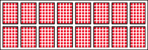
Figure 1. Example of an 8 character by 2 lines matrix display panel using 5x7 matrix characters.
Character matrix display panels are cheaper to build than graphic matrix panels because fewer LEDs are used. The example character panel (Figure 1) uses a 1-LED pitch between characters both vertically and horizontally for inter-character spacing. This spacing costs 8 LEDs per horizontal spacing, and 6 LEDs per vertical spacing for the equivalent graphic panel (Figure 2). Of course, the graphic panel is more versatile; smooth scrolling (pixel by pixel) is possible, graphics and larger text can be displayed, and so on.

Figure 2. Example of a 48 x 16 graphic matrix display panel.
Table 1. MAX6952 and MAX6953 Multiplex Drive to 4 Mono-color Cathode-Row Digits
Table 2. MAX6952 and MAX6953 Multiplex Drive to 2 Bi-Color Cathode-Row Digits
Taking a larger view of the multiplex drive scheme, it can be seen that the MAX6952/3 is actually driving a 14 x 10 LED matrix (Table 3). This large matrix is normally subdivided to suit the intended 4 mono-color digits (7 cathode rows, 5 anode columns) or 2 bi-color digits (7 cathode rows, 10 anode columns).
Table 3. MAX6952 and MAX6953 Multiplex Drive to an LED Matrix
Graphic panels are commonly built to octal sizes, in other words the number of pixels or LEDs along each side is a multiple of eight. The octal mapping simplifies data handling with 8 bit microprocessors, where the display's memory map is byte-wide. Also, a traditional standard for mono-spaced small fonts is a 5x7 font in an 8x8 font block. In this case, the 8x8 block provides whitespace around each character to separate characters (Figure 3). Of course, one of the advantages of graphic panels is that fonts can be designed to various sizes, with bold and italic, and the spacing can be made proportional, so 5x7 fonts are less important.

Figure 3. Example of a 5x7 font characters within 8x8 font blocks.
The smallest LED array built with 5x7 matrix blocks that also fits a block built with 8x8 matrix blocks is 40 x 56 pixels (Figure 4). This is called a matrix sub-block. Figure 4 shows the matrix sub-block as landscape format, which is the common orientation. The matrix sub-block rotated into portrait format instead.

Figure 4. Matrix sub-block; the smallest mapping of multiple 8x8 matrix displays to multiple 5x7 matrix displays.
The size of the target graphic panel should be an exact multiple of this matrix sub-block. If that can be achieved, the design will use the minimum number of MAX6952 or MAX6953 drivers, and the software driver can treat the display as an orthogonal array of these matrix sub-blocks.
There are a number of valid configurations for MAX6952 or MAX6953 drivers to drive the 5x7 elements within this matrix sub-block. Figures 5 and 6 show example driver configurations for mono-color and bi-color sub-blocks. It is now up to the panel designer to choose a graphic panel size that uses an integer multiple of the 40 x 56 pixel dimension. One last hint: landscape format sub-blocks can be combined to build a portrait panel, and vice-versa. For example, 2 rows of 6 side by side portrait panels constructs a 240 x 112 landscape panel.

Figure 5. Example of the MAX6952 or MAX6953 driver allocation for a mono-color matrix sub-block.

Figure 6. Example of the MAX6952 or MAX6953 driver allocation for a bi-color matrix sub-block.
This application note is one of two application notes that discuss the software and processor interface issues in the application of the MAX6952 and MAX6953 LED drivers to build an LED matrix graphic panel for message boards and animated graphic displays. This note covers the electrical aspects of the panel design; the other note, Software Control of the MAX6952 and MAX6953 LED Drivers in Graphic Applications, covers the software aspects of the panel design.
The MAX6952 and MAX6953 are 4-digit cathode-row 5x7 matrix LED display drivers that are controlled through a high-speed SPI (MAX6952) or I²C (MAX6953) serial interface. These drivers are primarily intended for character display applications where individual 5x7 matrix digits are physically spaced apart to form one or more character lines (Figure 1).

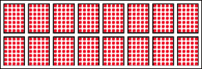
Figure 1. Example of an 8 character by 2 lines matrix display panel using 5x7 matrix characters.
Character matrix display panels are cheaper to build than graphic matrix panels because fewer LEDs are used. The example character panel (Figure 1) uses a 1-LED pitch between characters both vertically and horizontally for inter-character spacing. This spacing costs 8 LEDs per horizontal spacing, and 6 LEDs per vertical spacing for the equivalent graphic panel (Figure 2). Of course, the graphic panel is more versatile; smooth scrolling (pixel by pixel) is possible, graphics and larger text can be displayed, and so on.

Figure 2. Example of a 48 x 16 graphic matrix display panel.
Electrical Connection of the MAX6952 or MAX6953 to Graphic Displays
Each MAX6952 or MAX6953 conventionally drives either 4 mono-color 5x7 matrix cathode-row digits (Table 1), or 2 bi-color digits (Table 2). The multiplexing engine doesn't actually know or care whether mono-color or bi-color displays are used; bi-color digits are treated both electrically and in software as two mono-color digits.Table 1. MAX6952 and MAX6953 Multiplex Drive to 4 Mono-color Cathode-Row Digits
| Digit | O0 | O1 | O2 | O3 | O4 | O5 | O6 | O7 | O8 | O9 | O10 | O11 | O12 | O13 | O14 | O15 | O16 | O17 | O18 | O19 | O20 | O21 | O22 | O23 |
| 1 | Digit 0 rows (cathodes) R1 to R7 Digit 1 rows (cathodes) R1 to R7 |
Digit 0 columns (anodes) C1 to C5 |
Digit 1 columns (anodes) C1 to C5 | |||||||||||||||||||||
| 2 | Digit 2 rows (cathodes) R1 to R7 Digit 3 rows (cathodes) R1 to R7 |
Digit 2 columns (anodes) C1 to C5 |
Digit 3 columns (anodes) C1 to C5 | |||||||||||||||||||||
Table 2. MAX6952 and MAX6953 Multiplex Drive to 2 Bi-Color Cathode-Row Digits
| Digit | O0 | O1 | O2 | O3 | O4 | O5 | O6 | O7 | O8 | O9 | O10 | O11 | O12 | O13 | O14 | O15 | O16 | O17 | O18 | O19 | O20 | O21 | O22 | O23 |
| 1 | Digit 0 rows (cathodes) R1 to R7 | Digit 0 columns (anodes) C1 to C10 | ||||||||||||||||||||||
| - the 5 green anodes - | - the 5 red anodes - | |||||||||||||||||||||||
| 2 | Digit 1 rows (cathodes) R1 to R7 | Digit 1 columns (anodes) C1 to C10 | ||||||||||||||||||||||
| - the 5 green anodes - | - the 5 red anodes - | |||||||||||||||||||||||
Taking a larger view of the multiplex drive scheme, it can be seen that the MAX6952/3 is actually driving a 14 x 10 LED matrix (Table 3). This large matrix is normally subdivided to suit the intended 4 mono-color digits (7 cathode rows, 5 anode columns) or 2 bi-color digits (7 cathode rows, 10 anode columns).
Table 3. MAX6952 and MAX6953 Multiplex Drive to an LED Matrix
| Digit | O0 | O1 | O2 | O3 | O4 | O5 | O6 | O7 | O8 | O9 | O10 | O11 | O12 | O13 | O14 | O15 | O16 | O17 | O18 | O19 | O20 | O21 | O22 | O23 |
| 1 | Matrix rows (cathodes) R1 to R14 | Matrix columns (anodes) C1 to C10 | ||||||||||||||||||||||
Defining the LED Graphic Panel
A single MAX6952 or MAX6953 will drive an LED array up to 14 cathodes by 10 anodes, or multiple smaller arrays that fit into that limit (e.g., four 5x7 cathode row arrays). The best approach is to design the display system so that each MAX6952 or MAX6953 drives its own independent sub-block of the display matrix. The preferred display elements are therefore 5x7 matrix LEDs butted together (or equivalent using discrete LEDs), mono- or bi-color as desired.Graphic panels are commonly built to octal sizes, in other words the number of pixels or LEDs along each side is a multiple of eight. The octal mapping simplifies data handling with 8 bit microprocessors, where the display's memory map is byte-wide. Also, a traditional standard for mono-spaced small fonts is a 5x7 font in an 8x8 font block. In this case, the 8x8 block provides whitespace around each character to separate characters (Figure 3). Of course, one of the advantages of graphic panels is that fonts can be designed to various sizes, with bold and italic, and the spacing can be made proportional, so 5x7 fonts are less important.

Figure 3. Example of a 5x7 font characters within 8x8 font blocks.
The smallest LED array built with 5x7 matrix blocks that also fits a block built with 8x8 matrix blocks is 40 x 56 pixels (Figure 4). This is called a matrix sub-block. Figure 4 shows the matrix sub-block as landscape format, which is the common orientation. The matrix sub-block rotated into portrait format instead.

Figure 4. Matrix sub-block; the smallest mapping of multiple 8x8 matrix displays to multiple 5x7 matrix displays.
The size of the target graphic panel should be an exact multiple of this matrix sub-block. If that can be achieved, the design will use the minimum number of MAX6952 or MAX6953 drivers, and the software driver can treat the display as an orthogonal array of these matrix sub-blocks.
There are a number of valid configurations for MAX6952 or MAX6953 drivers to drive the 5x7 elements within this matrix sub-block. Figures 5 and 6 show example driver configurations for mono-color and bi-color sub-blocks. It is now up to the panel designer to choose a graphic panel size that uses an integer multiple of the 40 x 56 pixel dimension. One last hint: landscape format sub-blocks can be combined to build a portrait panel, and vice-versa. For example, 2 rows of 6 side by side portrait panels constructs a 240 x 112 landscape panel.

Figure 5. Example of the MAX6952 or MAX6953 driver allocation for a mono-color matrix sub-block.

Figure 6. Example of the MAX6952 or MAX6953 driver allocation for a bi-color matrix sub-block.
 电子发烧友App







评论