对于这个项目,你需要:
Raspberry Pi
2 x LED
跳线电缆
面包板
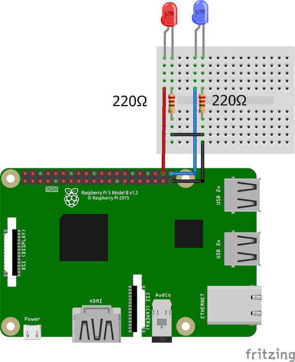
电路图和说明
电路图非常简单。我们只需要使用220欧姆电阻将两个LED连接到Raspberry Pi上的GPIO 20和21。将引脚连接到每个LED的正极,并将每个LED的负极与220欧姆电阻连接到地。

完整的Python代码
用于控制Raspberry Pi的GPIO的Python代码通过GUI应用程序的引脚可以在下面找到。将此代码复制并粘贴到新文件中,并使用文件扩展名保存:.py(例如,GUItest.py)。确保您位于同一目录中,然后使用命令 python GUItest.py 从终端运行程序。
import Tkinter as tk
import RPi.GPIO as GPIO
from time import sleep
GPIO21 = 21
GPIO20 = 20
GPIO.setmode(GPIO.BCM)
GPIO.setup(GPIO21, GPIO.OUT)
GPIO.setup(GPIO20, GPIO.OUT)
master = tk.Tk()
master.title(“GPIO Control”)
master.geometry(“300x100”)
GPIO21_state = True
GPIO20_State = True
def GPIO21button():
global GPIO21_state
if GPIO21_state == True:
GPIO.output(GPIO21, GPIO21_state)
GPIO21_state = False
ONlabel = tk.Label(master, text=“Turned ON”, fg=“green”)
ONlabel.grid(row=0, column=1)
else:
GPIO.output(GPIO21, GPIO21_state)
GPIO21_state = True
ONlabel = tk.Label(master, text=“Turned OFF”, fg=“red”)
ONlabel.grid(row=0, column=1)
def GPIO20button():
global GPIO20_State
if GPIO20_State == True:
GPIO.output(GPIO20, GPIO20_State)
GPIO20_State = False
OFFlabel = tk.Label(master, text=“Turned ON”, fg=“green”)
OFFlabel.grid(row=1, column=1)
else:
GPIO.output(GPIO20, GPIO20_State)
GPIO20_State = True
OFFlabel = tk.Label(master, text=“Turned OFF”, fg=“red”)
OFFlabel.grid(row=1, column=1)
ONbutton = tk.Button(master, text=“GPIO 21”, bg=“blue”, command=GPIO21button)
ONbutton.grid(row=0, column=0)
OFFbutton = tk.Button(master, text=“GPIO 20”,bg=“blue” , command=GPIO20button)
OFFbutton.grid(row=1, column=0)
Exitbutton = tk.Button(master, text=“Exit”,bg=“red”, command=master.destroy)
Exitbutton.grid(row=2, column=0)
master.mainloop()
代码演练
让我们来看看代码,看看每个部分的作用整个项目。
首先,我们为这个项目导入了所需的库。 Tkinter库帮助我们创建了GUI应用程序,RPi.GPIO库控制着Raspberry Pi的GPIO引脚。
import Tkinter as tk
import RPi.GPIO as GPIO
from time import sleep
然后我们使用BCM引脚编号为我们的LED初始化了GPIO引脚21和20,将这些引脚声明为输出。
GPIO21 = 21
GPIO20 = 20
GPIO.setmode(GPIO.BCM)
GPIO.setup(GPIO21, GPIO.OUT)
GPIO.setup(GPIO20, GPIO.OUT)
之后,我们创建了Tk根小部件。只能有一个根小部件,它必须在任何其他小部件之前创建。
然后我们重命名该窗口的标题并定义其大小。
master = tk.Tk()
master.title(“GPIO Control”)
master.geometry(“300x100”)
当GPIO按下21按钮,它将查找以前的状态。如果前一个状态为真(高状态),它将使其为假(低状态),反之亦然。
按钮旁边还有一个标签,告诉我们LED是否为高电平或LOW。
def GPIO21button():
global GPIO21_state
if GPIO21_state == True:
GPIO.output(GPIO21, GPIO21_state)
GPIO21_state = False
ONlabel = tk.Label(master, text=“Turned ON”, fg=“green”)
ONlabel.grid(row=0, column=1)
else:
GPIO.output(GPIO21, GPIO21_state)
GPIO21_state = True
ONlabel = tk.Label(master, text=“Turned OFF”, fg=“red”)
ONlabel.grid(row=0, column=1)
GPIO 20按钮的工作方式类似:
def GPIO20button():
global GPIO20_State
if GPIO20_State == True:
GPIO.output(GPIO20, GPIO20_State)
GPIO20_State = False
OFFlabel = tk.Label(master, text=“Turned ON”, fg=“green”)
OFFlabel.grid(row=1, column=1)
else:
GPIO.output(GPIO20, GPIO20_State)
GPIO20_State = True
OFFlabel = tk.Label(master, text=“Turned OFF”, fg=“red”)
OFFlabel.grid(row=1, column=1)
最后,我们创建了三个按钮。其中两个控制GPIO引脚20和21,第三个是退出按钮。
ONbutton = tk.Button(master, text=“GPIO 21”, bg=“blue”, command=GPIO21button)
ONbutton.grid(row=0, column=0)
OFFbutton = tk.Button(master, text=“GPIO 20”,bg=“blue” , command=GPIO20button)
OFFbutton.grid(row=1, column=0)
Exitbutton = tk.Button(master, text=“Exit”,bg=“red”, command=master.destroy)
Exitbutton.grid(row=2, column=0)
-
树莓派
+关注
关注
117文章
1711浏览量
105930 -
gpio引脚
+关注
关注
0文章
8浏览量
2651
发布评论请先 登录
相关推荐
树莓派传感器使用方法 树莓派 Raspberry Pi 4优缺点
使用树莓派实现远程控制的技巧
树莓派开发的最佳编程语言选择
树莓派gpio有什么用,树莓派gpio接口及编程方法
什么是树莓派?树莓派是什么架构的
类树莓派网关:物联网应用的新标杆


 怎样用Tkinter控制树莓派GPIO引脚


评论