 如何训练Wekinator控制Arduino

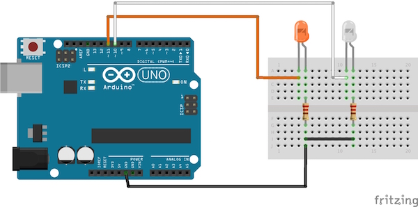
电路图
将Arduino的引脚11连接到橙色LED的正极引线,通过220欧姆电阻将LED的负极引线连接到Arduino的地。类似地,通过220欧姆电阻将白色LED的正极引线连接到Arduino的引脚10和LED的负极引线连接到Arduino。
程序入门
首先,在Arduino IDE中加载下面为Arduino提供的代码。然后上传给定代码以在IDE中处理。
之后,打开Wekinator并将输入更改为1并输出为2并离开另一个选项。

点击“下一步”,会出现一个新窗口。现在从处理的输入窗口,单击橙色框,在Wekinator中,在输出-1框中输入1,然后开始录制半秒。

现在,单击处理中的白色框,在Wekinator中,在输出-1框中输入0并在输出-2框中输入1并开始记录半秒。

现在点击“Train”,然后点击“Run”。现在,当您点击橙色框时,连接到引脚11的LED将亮起,当您单击白色框时,连接到Arduino引脚10的LED将亮起。
Arduino代码
代码用注释解释。
#include //Including the library that will help us in receiving and sending the values from processing
ValueReceiver《2》 receiver; /*Creating the receiver that will receive up to 2 values.
Put the number of values to synchronize in the brackets */
/* The below two variables will be synchronized in the processing
and they should be same on both sides. */
int output;
int output1;
// Initializing the pins for led‘s
int orange_led = 11;
int white_led = 10;
void setup()
{
/* Starting the serial communication because we are communicating with the
Arduino through serial. The baudrate should be same as on the processing side. */
Serial.begin(19200);
pinMode(white_led, OUTPUT);
pinMode(orange_led, OUTPUT);
// Synchronizing the variables with the processing. The variables must be int type.
receiver.observe(output);
receiver.observe(output1);
}
void loop()
{
// Receiving the output from the processing.
receiver.sync();
// Matching the received output to light up led’s
if (output == 1)
{
digitalWrite(orange_led, HIGH);
}
else if (output == 0)
{
digitalWrite(orange_led, LOW);
}
if (output1 == 1)
{
digitalWrite(white_led, HIGH);
}
else if(output1 == 0)
{
digitalWrite(white_led, LOW);
}
}
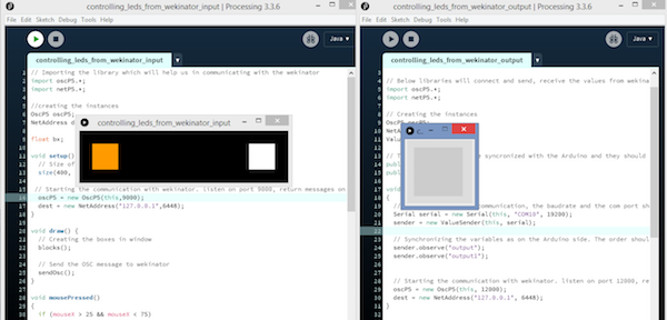
处理代码(输入到Wekinator)
// Importing the library which will help us in communicating with the wekinator
import oscP5.*;
import netP5.*;
//creating the instances
OscP5 oscP5;
NetAddress dest;
float bx;
void setup() {
// Size of output window
size(400, 100, P3D);
// Starting the communication with wekinator. listen on port 9000, return messages on port 6448
oscP5 = new OscP5(this,9000);
dest = new NetAddress(“127.0.0.1”,6448);
}
void draw() {
// Creating the boxes in window
blocks();
// Send the OSC message to wekinator
sendOsc();
}
void mousePressed()
{
if (mouseX 》 25 && mouseX 《 75)
{
bx=1;
}
if (mouseX 》 325 && mouseX 《 375)
{
bx=2;
}
}
void sendOsc() {
OscMessage msg = new OscMessage(“/wek/inputs”);
msg.add((float)bx);
oscP5.send(msg, dest);
}
void blocks()
{
background(0);
fill(255, 155, 0);
rect(25, 25, 50, 50);
fill(255, 255, 255);
rect(325, 25, 50, 50);
}
处理代码(Wekinator的输出)
import vsync.*; // Importing the library that will help us in sending and receiving the values from the Arduino
import processing.serial.*; // Importing the serial library
// Below libraries will connect and send, receive the values from wekinator
import oscP5.*;
import netP5.*;
// Creating the instances
OscP5 oscP5;
NetAddress dest;
ValueSender sender;
// These variables will be syncronized with the Arduino and they should be same on the Arduino side.
public int output;
public int output1;
void setup()
{
// Starting the serial communication, the baudrate and the com port should be same as on the Arduino side.
Serial serial = new Serial(this, “COM10”, 19200);
sender = new ValueSender(this, serial);
// Synchronizing the variables as on the Arduino side. The order should be same.
sender.observe(“output”);
sender.observe(“output1”);
// Starting the communication with wekinator. listen on port 12000, return messages on port 6448
oscP5 = new OscP5(this, 12000);
dest = new NetAddress(“127.0.0.1”, 6448);
}
// Recieve OSC messages from Wekinator
void oscEvent(OscMessage theOscMessage) {
if (theOscMessage.checkAddrPattern(“/wek/outputs”) == true) {
// Receiving the output from wekinator
float value = theOscMessage.get(0).floatValue(); // First output
float value1 = theOscMessage.get(1).floatValue(); // Second output
// Converting the output to int type
output = int(value);
output1 = int(value1);
}
}
void draw()
{
// Nothing to be drawn for this example
}
-
Arduino
+关注
关注
190文章
6527浏览量
197530
发布评论请先 登录
BTN9970/BTN9990电机控制盾牌:Arduino评估利器
探索用于Arduino的TLE94112ES直流电机控制盾牌
贸泽电子开售全新Arduino UNO Q单板计算机
在Ubuntu20.04系统中训练神经网络模型的一些经验
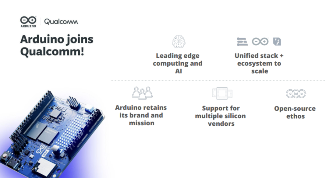
高通宣布收购 Arduino,加速普及前沿边缘计算与 AI 技术
如何在 NuMaker-IoT-M467 板上使用 Arduino IDE 控制 Wi-Fi 模块?
如何用Arduino Nano/UNO R3开发板给另一个Arduino IDE不能下载的Arduino Nano/UNO R3开发板重新烧录引导程序bootlaoder
OCR识别训练完成后给的是空压缩包,为什么?
免费分享Arduino入门+进阶(全套例程+书籍)


评论