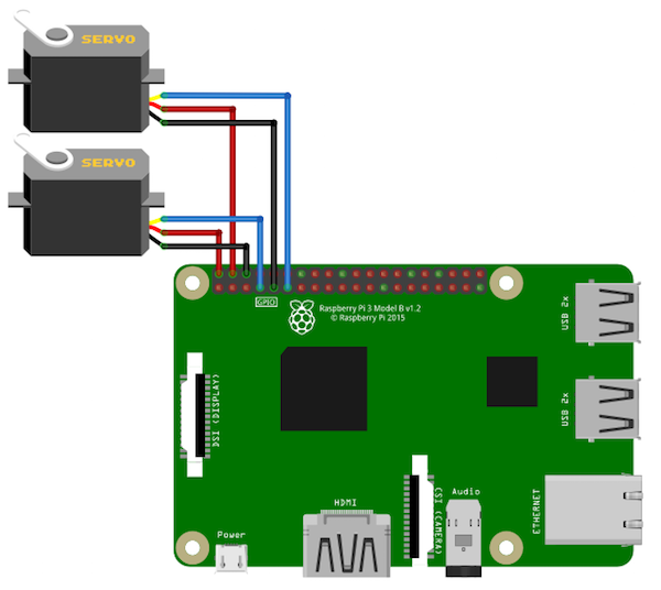
电路图
将两个伺服电机的红线连接到Raspberry Pi的5V GPIO引脚。然后将两个伺服系统的黑线连接到Raspberry Pi的地面。最后,将其中一个伺服电机的黄色线连接到Raspberry Pi的GPIO 4,将另一个伺服的黄色线连接到Raspberry Pi的GPIO 17。
如何运行程序
《首先,您需要从Wekinator的快速演练页面下载草图。
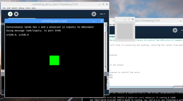
从那里下载屏幕上的鼠标控制示例。解压缩并在处理中打开草图。该草图将为Wekinator提供输入。您将需要另一个草图来获取Wekinator的输出。该草图的代码在本文末尾。将其粘贴到处理中并运行它。两个处理输出窗口如下所示:
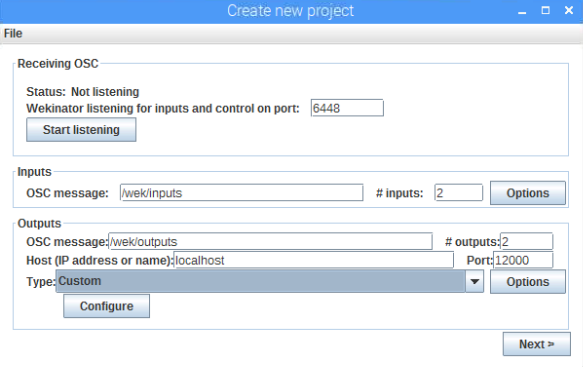
现在打开Wekinator并进行如下图所示的设置。将输入和输出设置为2,然后将类型设置为“自定义”,然后单击“配置”。
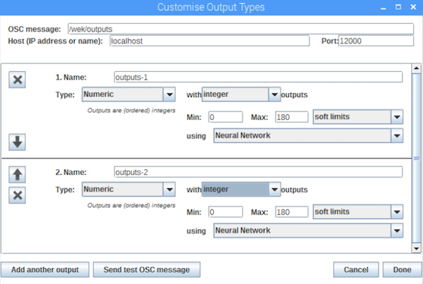
当您点击“配置”时,一个新的窗口将打开。更改该窗口中的设置,如下图所示。
现在将处理窗口中的绿框拖到左侧中央并设置设置在Wekinator窗口中,如下所示。之后,开始录制半秒。
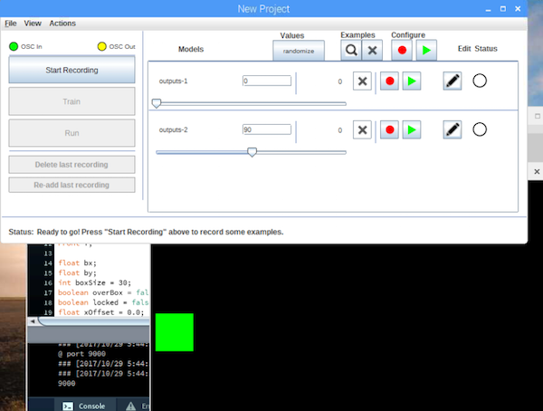
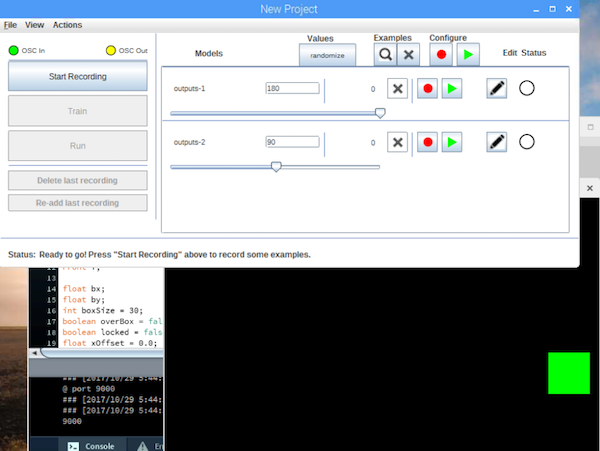
现在将处理窗口中的绿色框拖到右侧中央,然后在Wekinator窗口如下图所示。之后,开始录制半秒。
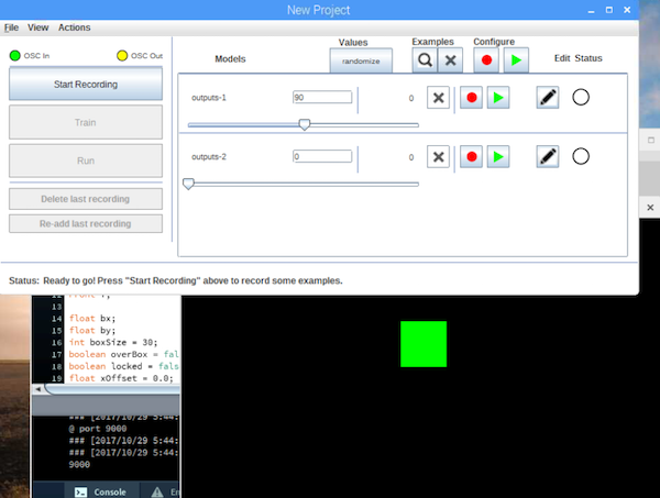
现在将处理窗口中的绿框拖到中心顶部并在Wekinator中设置设置窗口如下图所示。之后,开始录制半秒。
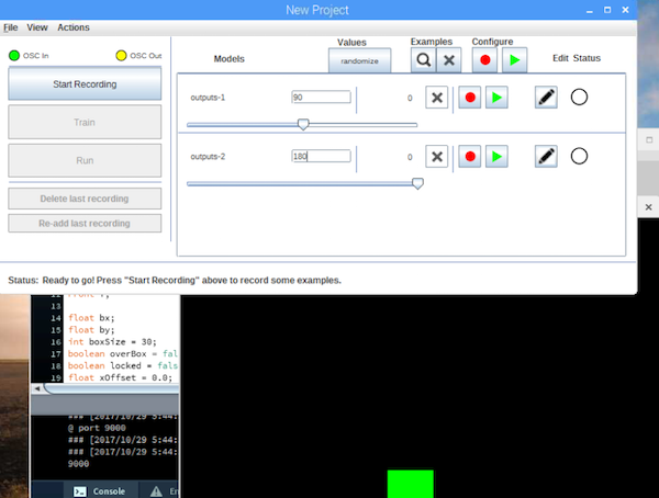
现在将处理窗口中的绿色框拖到底部中心一侧,然后在Wekinator窗口如下图所示。之后,开始录制半秒。
单击“Train”,然后单击“Run”。现在当您在处理窗口中拖动绿色框时,连接到Raspberry Pi的GPIO引脚的伺服器将根据它移动。
处理代码
import processing.io.*; // Importing the library to control the GPIO pins of raspberry pi
// Below libraries will help in connecting and sending, receiving the values from wekinator
import oscP5.*;
import netP5.*;
// Creating the instances
OscP5 oscP5;
NetAddress dest;
// Variable to store the output
public int output;
public int output1;
// Creating the instances to control the servo
SoftwareServo servo1;
SoftwareServo servo2;
void setup()
{
// Initializing the pins for servo
servo1 = new SoftwareServo(this);
servo1.attach(17);
servo2 = new SoftwareServo(this);
servo2.attach(4);
// Starting the communication with wekinator. listen on port 12000, return messages on port 6448
oscP5 = new OscP5(this, 12000);
dest = new NetAddress(“127.0.0.1”, 6448);
}
// Recieve OSC messages from Wekinator
void oscEvent(OscMessage theOscMessage) {
if (theOscMessage.checkAddrPattern(“/wek/outputs”) == true) {
// Receiving the output from wekinator
float value = theOscMessage.get(0).floatValue(); // First output
float val = theOscMessage.get(1).floatValue();
// Converting the output to int type
output = int(value);
output1 = int(val);
}
}
void draw()
{
if (output 》 0 && output 《 180)
{
servo1.write(output);
}
if (output1 》 0 && output1 《 180)
{
servo2.write(output1);
}
}
-
伺服电机
+关注
关注
85文章
2064浏览量
58461 -
树莓派
+关注
关注
117文章
1713浏览量
106016
发布评论请先 登录
相关推荐
用树莓派2控制一个LED灯
怎样用ArduinoUNO和Wekinator控制伺服电机
怎样用Wekinator控制与树莓派连接的LED
树莓派使用Python控制步进电机


 怎样用Wekinator控制与树莓派连接的伺服电机


评论