第1步:材料
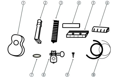

结构材料:
DIY ukelele安装套件(可能是另一种不同的套件)由以下组成:
1- Body。
2-neck。
3-Saddle
4-Rope Support
5-Bridge
6-String nut 。
7-机头固定环(x4)。
8机头(x4)。
9-机头安装螺丝(x8)用于机桥(x2)的10个安装螺钉。
11-用于桥接安装螺钉(x2)的盖帽。
12弦( x4)。
电子资料:
NANO Arduino。
Leds轮WS2812。
加速度计BMA220(可选)。
电池连接器。
9V电池。
转移。
其他
木器清漆。
魔术贴。
焊锡。
用于上漆的保护性塑料。
热熔硅胶。
工具:
激光雕刻。
砂纸
星形螺丝刀。
画笔。
热熔枪。
锡烙铁。
第2步:自定义尤克里里琴


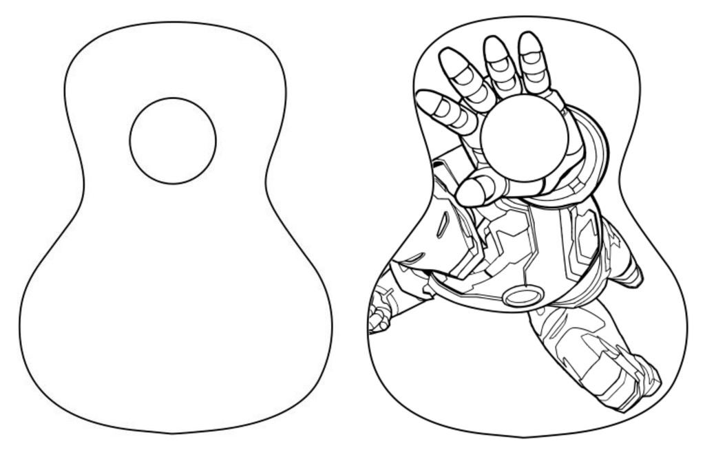

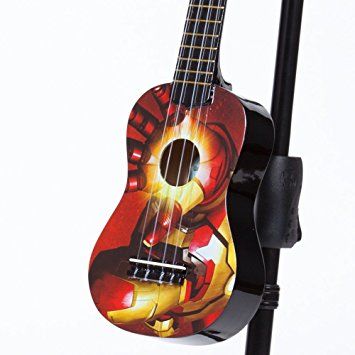
为了使我们的夏威夷四弦琴成型,我们可以在身体上用激光切割机雕刻图纸。在没有该工具的情况下,我们可以绘制它。
我们选择的图片是第一个出现的图片。
首先,我们必须设计绘图模板来进行雕刻。
为了实现这一点,我们将使用一个名为“Inkscape”的软件,我们可以从这个链接获得:https://inkscape.org/es/descargas/。
使用它,我们必须调整我们想要使用的图片,就像我们在第二张图片中显示的那样。您可以看到我们已经旋转了初始图像,可以用仪器的圆圈调整手的cicle。就像我们之前说的那样,你可以放任何图像。
第3步:使用Inkscape对图像进行矢量化


我们将看到如何从像素图创建矢量文件(jpg,png,Inkscape可以打开的任何栅格格式)。
Inkscape Inkscape是一个开源矢量图形编辑器,正如标题所暗示的,这是我将用来矢量化徽标的工具。矢量化步骤这些步骤对于我们可能想要进行的任何矢量化都是常见的。
在Inkscape中打开图像
打开跟踪位图工具路径 - 》跟踪位图
围绕跟踪位图选项进行游戏
运行跟踪
清理结果(如有必要)
注意“游戏”部分。我不是追踪专家,所以我把这个工具当作一个带旋钮和灯光的黑盒子,扭曲和改变直到我得到最好的结果
第4步:徽标雕刻


为此,重要的是要有一个表面的轮廓,其上的雕刻将制作。
为了制作雕刻,我们将使用‘T2Laser’软件。我们可以从以下网站获取此软件:http://descargar.cnet.com/windows/t2-laser/3260-2.。.
一旦我们打开软件,我们必须加载图像我们在最后一步创建了。然后,按“控制激光”按钮,出现cnc控件。
两张照片显示了我们激光切割机雕刻的过程和结果。
步骤5:打磨和上漆


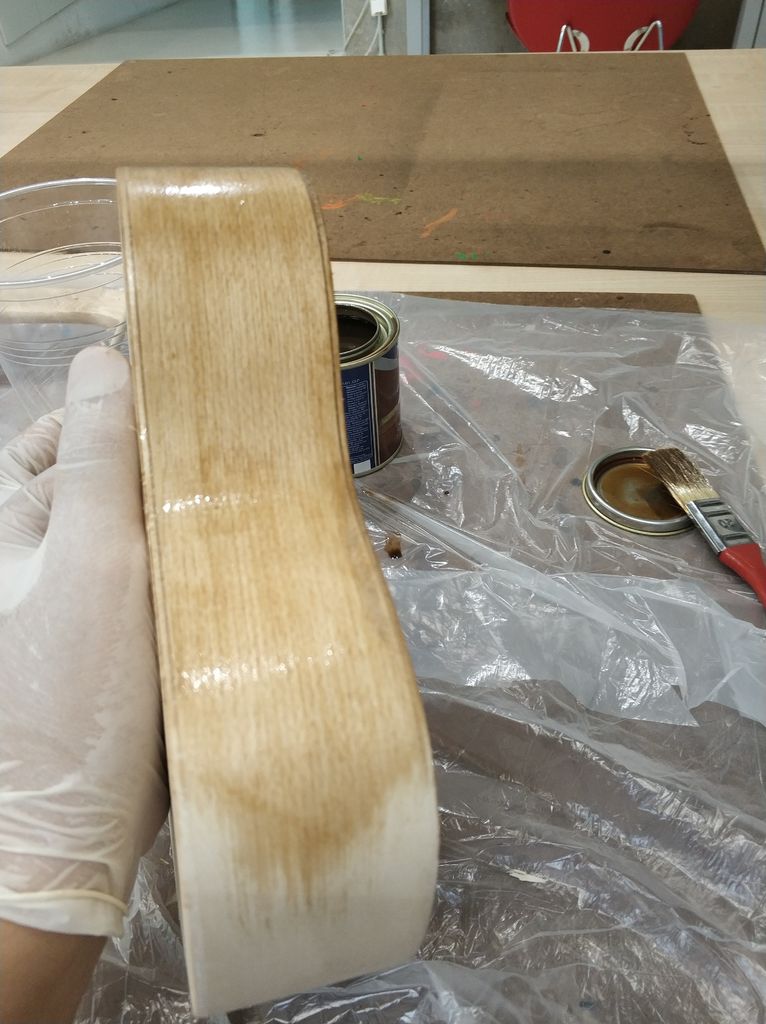

为了让我们的夏威夷四弦琴明亮,并且没有粗糙的层,我们可以顺利地打磨构成我们乐器的两个部分,因为我们可能会损坏已经制作的图纸(如果您选择绘制尤克里里琴,则必须先将其打磨)。然后我们将清漆我们的两个部分,使它们获得更深的颜色,木材呈现出更大的阻力。我们可以使用普通的木材清漆,它不需要特殊。
一旦我们有清漆,我们将它与少量溶剂混合,使其溶解一点。接下来,我们用刷子将混合物涂在颈部和仪器的主体上,让它干燥。
如果我们发现产品需要第二层涂层,我们可以将这两个部分打磨一下重新涂抹一层稀释的清漆。
**预防措施:清漆是一种化学产品,因此必须在通风处进行此过程,戴上口罩以避免吸入异味和护目镜。
我们需要能够正常工作的材料是照片中出现的材料。主要是我们将使用刷子,清漆罐(在我们的情况下是红色),一点溶剂和视觉保护。最重要的是在通风良好的空间工作。
第6步:硬件
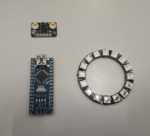


我们带有Arduino,acelerometer和带LED指示灯的铭牌将在一个小支架中引入,以避免所有组件在仪器中移动。
我们还添加了一个电池座和一个开关,使其更舒适,我们不使用仪器时也不会耗尽电池。我们将这个支架用一块维可牢尼龙搭扣(它也适用于硅胶和热熔枪)连接到尤克里里琴琴体的内表面。
另一方面,LED轮小于孔,所以它会下降。已经设计了一个支持,以便它可以很好地执行其功能。
步骤7:软件


为了给我们的夏威夷四弦琴做一个特殊的装饰,我们可以通过一个LED轮来增加灯光效果。我们将使用WS2812,但您可以按照数据表的说明使用任何其他产品。我们也将使用一个acelerometer(BMA220),它可以让我们产生重力效应。
事实上,我们将有4个光源,包括在Arduino的名为“Adafruit”的计算机库中。为此,我们必须在三个组件之间做出正确的共识:Arduino NANO,WS2812和BMA220,就像出现在第一张图片中一样。
红色线用于供电,GND黑色和其余部分是正确操作所必需的连接。
我们用于灯具的代码附在一个名为“play_of_light_v0”的文件中。鲍”。确保已包含必要的库以正确操作程序。我们在电路外部添加的电池必须具有9V的最小电压,我们必须确保它能够提供为整个电路供电所需的最小电流。
//Variables contador e interrupción
int counter;
//Variables Ejemplo gravedad
#include
#include
#include
#define NUMBER_OF_LEDS_ON_RING 16
#define NEOPIXEL_RING_DATA_PIN 9
byte Version[3];
int8_t x_data;
int8_t y_data;
int8_t z_data;
byte range=0x00;
float divi=16;
float x,y,z;
float pi = 3.14159265359;
float nx,ny,angle;
int led, previousLed;
QueueList ledQueue;
Adafruit_NeoPixel neoring = Adafruit_NeoPixel(NUMBER_OF_LEDS_ON_RING, NEOPIXEL_RING_DATA_PIN, NEO_GRB + NEO_KHZ800);
//Variables Luces arcoiris
#include
#ifdef __AVR__
#include
#endif
#define PIN 9
// Parameter 1 = number of pixels in strip
// Parameter 2 = Arduino pin number (most are valid)
// Parameter 3 = pixel type flags, add together as needed:
// NEO_KHZ800 800 KHz bitstream (most NeoPixel products w/WS2812 LEDs)
// NEO_KHZ400 400 KHz (classic ‘v1’ (not v2) FLORA pixels, WS2811 drivers)
// NEO_GRB Pixels are wired for GRB bitstream (most NeoPixel products)
// NEO_RGB Pixels are wired for RGB bitstream (v1 FLORA pixels, not v2)
// NEO_RGBW Pixels are wired for RGBW bitstream (NeoPixel RGBW products)
Adafruit_NeoPixel strip = Adafruit_NeoPixel(16, PIN, NEO_GRB + NEO_KHZ800);
// IMPORTANT: To reduce NeoPixel burnout risk, add 1000 uF capacitor across
// pixel power leads, add 300 - 500 Ohm resistor on first pixel‘s data input
// and minimize distance between Arduino and first pixel. Avoid connecting
// on a live circuit.。.if you must, connect GND first.
//Variables Rueda de colores
// NeoPixel Ring simple sketch (c) 2013 Shae Erisson
// released under the GPLv3 license to match the rest of the AdaFruit NeoPixel library
#include
#ifdef __AVR__
#include
#endif
// Which pin on the Arduino is connected to the NeoPixels?
// On a Trinket or Gemma we suggest changing this to 1
#define PIN 9
// How many NeoPixels are attached to the Arduino?
#define NUMPIXELS 16
// When we setup the NeoPixel library, we tell it how many pixels, and which pin to use to send signals.
// Note that for older NeoPixel strips you might need to change the third parameter--see the strandtest
// example for more information on possible values.
Adafruit_NeoPixel pixels = Adafruit_NeoPixel(NUMPIXELS, PIN, NEO_GRB + NEO_KHZ800);
int delayval = 50; // delay for 50ms
//Variables colores aleatorios
#include
#ifdef __AVR__
#include
#endif
#define PIN 9
#define NUM_LEDS 16
#define BRIGHTNESS 200
//Adafruit_NeoPixel strip = Adafruit_NeoPixel(NUM_LEDS, PIN, NEO_GRBW + NEO_KHZ800);
byte neopix_gamma[] = {
0, 0, 0, 0, 0, 0, 0, 0, 0, 0, 0, 0, 0, 0, 0, 0,
0, 0, 0, 0, 0, 0, 0, 0, 0, 0, 0, 0, 1, 1, 1, 1,
1, 1, 1, 1, 1, 1, 1, 1, 1, 2, 2, 2, 2, 2, 2, 2,
2, 3, 3, 3, 3, 3, 3, 3, 4, 4, 4, 4, 4, 5, 5, 5,
5, 6, 6, 6, 6, 7, 7, 7, 7, 8, 8, 8, 9, 9, 9, 10,
10, 10, 11, 11, 11, 12, 12, 13, 13, 13, 14, 14, 15, 15, 16, 16,
17, 17, 18, 18, 19, 19, 20, 20, 21, 21, 22, 22, 23, 24, 24, 25,
25, 26, 27, 27, 28, 29, 29, 30, 31, 32, 32, 33, 34, 35, 35, 36,
37, 38, 39, 39, 40, 41, 42, 43, 44, 45, 46, 47, 48, 49, 50, 50,
51, 52, 54, 55, 56, 57, 58, 59, 60, 61, 62, 63, 64, 66, 67, 68,
69, 70, 72, 73, 74, 75, 77, 78, 79, 81, 82, 83, 85, 86, 87, 89,
90, 92, 93, 95, 96, 98, 99,101,102,104,105,107,109,110,112,114,
115,117,119,120,122,124,126,127,129,131,133,135,137,138,140,142,
144,146,148,150,152,154,156,158,160,162,164,167,169,171,173,175,
177,180,182,184,186,189,191,193,196,198,200,203,205,208,210,213,
215,218,220,223,225,228,231,233,236,239,241,244,247,249,252,255 };
///////////////////////////////////////////////////////////////////////////////////
//////////////////////////////////////////////////////////////////////////////////
/METODO SETUP
void setup()
{
//Código: Dirección de la gravedad
neoring.begin();
neoring.setBrightness(200);
Serial.begin(9600);
Wire.begin();
Wire.beginTransmission(0x0A); // address of the accelerometer
// range settings
Wire.write(0x22); //register address
Wire.write(range); //can be set at“0x00”“0x01”“0x02”“0x03”, refer to Datashhet on wiki
// low pass filter
Wire.write(0x20); //register address
Wire.write(0x05); //can be set at“0x05”“0x04”。..。..“0x01”“0x00”, refer to Datashhet on wiki
Wire.endTransmission();
//Codigo; Luces Arcoiris
// This is for Trinket 5V 16MHz, you can remove these three lines if you are not using a Trinket
#if defined (__AVR_ATtiny85__)
if (F_CPU == 16000000) clock_prescale_set(clock_div_1);
#endif
// End of trinket special code
strip.begin();
strip.show(); // Initialize all pixels to ’off‘
//Código Rueda de colores
// This is for Trinket 5V 16MHz, you can remove these three lines if you are not using a Trinket
#if defined (__AVR_ATtiny85__)
if (F_CPU == 16000000) clock_prescale_set(clock_div_1);
#endif
// End of trinket special code
pixels.begin(); // This initializes the NeoPixel library.
//Codigo Interrupcion
counter = 1;
//Codigo Colores varios
// This is for Trinket 5V 16MHz, you can remove these three lines if you are not using a Trinket
#if defined (__AVR_ATtiny85__)
if (F_CPU == 16000000) clock_prescale_set(clock_div_1);
#endif
// End of trinket special code
strip.setBrightness(BRIGHTNESS);
strip.begin();
strip.show(); // Initialize all pixels to ’off‘
}
///////////////////////////////////////////////////////////////////////////////////
//////////////////////////////////////////////////////////////////////////////////
/Bucle infinito
void loop() {
//Caso 1: Juego de luces de la gravedad;
if(counter == 1){
for(int i=0;i《100;i++){
switch(range) //change the data dealing method based on the range u’ve set
{
case 0x00:divi=16; break;
case 0x01:divi=8; break;
case 0x02:divi=4; break;
case 0x03:divi=2; break;
default: Serial.println(“range setting is Wrong,range:from 0to 3.Please check!”);while(1);
}
AccelerometerInit();
delay(100);
nx=x/2;
ny=y/2;
angle=atan((ny/nx))*180/pi;
if(angle 》 0.0){
if(nx《0.0)
angle+=180;
}
else{
if(ny 》 0.0)
angle+=180;
else
angle += 360;
}//end else
if(angle == 360.0)
angle = 0.0;
led = circularize(angle / (360 / NUMBER_OF_LEDS_ON_RING));
// make led movement smooth
if(previousLed == led){
// nothing to do
}
else if (counterClockwiseDistanceBetweenLeds(previousLed, led) 《= 8)
led = circularize(previousLed + 1);
else
led = circularize(previousLed - 1);
ledQueue.push(led);
makeLightShow();
previousLed = led;
delay(25);
}
counter = 2;
}//End if counter==1
//Caso 2: Codigo del juego de luces del arcoiris
else if(counter == 2){
for(int j=0; j《5;j++){
// Some example procedures showing how to display to the pixels:
colorWipe1(strip.Color(255, 0, 0), 50); // Red
colorWipe1(strip.Color(0, 255, 0), 50); // Green
colorWipe1(strip.Color(0, 0, 255), 50); // Blue
colorWipe1(strip.Color(0, 0, 0, 255), 50); // White RGBW
// Send a theater pixel chase in.。.
theaterChase(strip.Color(127, 127, 127), 50); // White
theaterChase(strip.Color(127, 0, 0), 50); // Red
theaterChase(strip.Color(0, 0, 127), 50); // Blue
rainbow(5);
rainbowCycle(5);
theaterChaseRainbow(5);
}
counter = 3;
}//End if counter==2
//Caso 3: Luces Aleatorias
else if(counter == 3){
for(int k=0;k《50;k++){
// For a set of NeoPixels the first NeoPixel is 0, second is 1, all the way up to the count of pixels minus one.
int a=random(255);
int b=random(255);
int c=random(255);
for(int i=0;i
// pixels.Color takes RGB values, from 0,0,0 up to 255,255,255
pixels.setPixelColor(i, pixels.Color(a,b,c)); // Moderately bright green color.
pixels.show(); // This sends the updated pixel color to the hardware.
delay(delayval); // Delay for a period of time (in milliseconds)。
}
a=random(255);
b=random(255);
c=random(255);
for(int i=NUMPIXELS;i》0;i--){
// pixels.Color takes RGB values, from 0,0,0 up to 255,255,255
pixels.setPixelColor(i, pixels.Color(a,b,c)); // Moderately bright green color.
pixels.show(); // This sends the updated pixel color to the hardware.
delay(delayval); // Delay for a period of time (in milliseconds)。
}
}
counter = 4;
}
else if(counter == 4){
for(int g=0;g《=6;g++){
// Some example procedures showing how to display to the pixels:
colorWipe(strip.Color(255, 0, 0), 50); // Red
colorWipe(strip.Color(0, 255, 0), 50); // Green
colorWipe(strip.Color(0, 0, 255), 50); // Blue
colorWipe(strip.Color(0, 0, 0, 255), 50); // White
whiteOverRainbow(20,75,5);
pulseWhite(5);
// fullWhite();
// delay(2000);
rainbowFade2White(3,3,1);
}
counter = 1;
}
}
///////////////////////////////////////////////////////////////////////////////////
//////////////////////////////////////////////////////////////////////////////////
/Metodos del Ejemplo de la gravedad
void AccelerometerInit()
{
Wire.beginTransmission(0x0A); // address of the accelerometer
// reset the accelerometer
Wire.write(0x04); // X data
Wire.endTransmission();
Wire.requestFrom(0x0A,1); // request 6 bytes from slave device #2
while(Wire.available()) // slave may send less than requested
{
Version[0] = Wire.read(); // receive a byte as characte
}
x_data=(int8_t)Version[0]》》2;
Wire.beginTransmission(0x0A); // address of the accelerometer
// reset the accelerometer
Wire.write(0x06); // Y data
Wire.endTransmission();
Wire.requestFrom(0x0A,1); // request 6 bytes from slave device #2
while(Wire.available()) // slave may send less than requested
{
Version[1] = Wire.read(); // receive a byte as characte
}
y_data=(int8_t)Version[1]》》2;
Wire.beginTransmission(0x0A); // address of the accelerometer
// reset the accelerometer
Wire.write(0x08); // Z data
Wire.endTransmission();
Wire.requestFrom(0x0A,1); // request 6 bytes from slave device #2
while(Wire.available()) // slave may send less than requested
{
Version[2] = Wire.read(); // receive a byte as characte
}
z_data=(int8_t)Version[2]》》2;
x=(float)x_data/divi;
y=(float)y_data/divi;
z=(float)z_data/divi;
Serial.print(“X=”);
Serial.print(x); // print the character
Serial.print(“ ”);
Serial.print(“Y=”);
Serial.print(y); // print the character
Serial.print(“ ”);
Serial.print(“Z=”); // print the character
Serial.println(z);
}
int circularize(int pos){
if(pos 》= NUMBER_OF_LEDS_ON_RING)
return(pos - NUMBER_OF_LEDS_ON_RING);
else if(pos 《 0)
return(pos + NUMBER_OF_LEDS_ON_RING);
else
return(pos);
}
int distance;
int counterClockwiseDistanceBetweenLeds(int prevPos, int nextPos){
distance = nextPos - prevPos;
if(distance 《 0)
distance += NUMBER_OF_LEDS_ON_RING;
return(distance);
}
int ledPosition, currentQueueSize;
#define NUMBER_OF_LEDS_TO_SHINE 10
int brightnessStep = 255/NUMBER_OF_LEDS_TO_SHINE;
void makeLightShow(){
for(int j = 0; j 《 NUMBER_OF_LEDS_ON_RING; j++)
neoring.setPixelColor(j, 0, 0, 0);
currentQueueSize = ledQueue.count();
for(int k = 0; k 《 currentQueueSize; k++){
ledPosition = ledQueue.pop();
neoring.setPixelColor(ledPosition, 0, (brightnessStep * k), 0);
if((k == 0 && currentQueueSize 《 NUMBER_OF_LEDS_TO_SHINE) || k 》 0)
ledQueue.push(ledPosition);
}
neoring.show();
}
///////////////////////////////////////////////////////////////////////////////////
//////////////////////////////////////////////////////////////////////////////////
/Metodos del juego de luces del arcoiris
// Fill the dots one after the other with a color
void colorWipe(uint32_t c, uint8_t wait) {
for(uint16_t i=0; i
void rainbow(uint8_t wait) {
uint16_t i, j;
for(j=0; j《256; j++) {
for(i=0; i
// Slightly different, this makes the rainbow equally distributed throughout
void rainbowCycle(uint8_t wait) {
uint16_t i, j;
for(j=0; j《256*5; j++) { // 5 cycles of all colors on wheel
for(i=0; i《 strip.numPixels(); i++) {
strip.setPixelColor(i, Wheel(((i * 256 / strip.numPixels()) + j) & 255));
}
strip.show();
delay(wait);
}
}
//Theatre-style crawling lights.
void theaterChase(uint32_t c, uint8_t wait) {
for (int j=0; j《10; j++) { //do 10 cycles of chasing
for (int q=0; q 《 3; q++) {
for (uint16_t i=0; i 《 strip.numPixels(); i=i+3) {
strip.setPixelColor(i+q, c); //turn every third pixel on
}
strip.show();
delay(wait);
for (uint16_t i=0; i 《 strip.numPixels(); i=i+3) {
strip.setPixelColor(i+q, 0); //turn every third pixel off
}
}
}
}
//Theatre-style crawling lights with rainbow effect
void theaterChaseRainbow(uint8_t wait) {
for (int j=0; j 《 256; j++) { // cycle all 256 colors in the wheel
for (int q=0; q 《 3; q++) {
for (uint16_t i=0; i 《 strip.numPixels(); i=i+3) {
strip.setPixelColor(i+q, Wheel( (i+j) % 255)); //turn every third pixel on
}
strip.show();
delay(wait);
for (uint16_t i=0; i 《 strip.numPixels(); i=i+3) {
strip.setPixelColor(i+q, 0); //turn every third pixel off
}
}
}
}
// Input a value 0 to 255 to get a color value.
// The colours are a transition r - g - b - back to r.
uint32_t Wheel(byte WheelPos) {
WheelPos = 255 - WheelPos;
if(WheelPos 《 85) {
return strip.Color(255 - WheelPos * 3, 0, WheelPos * 3);
}
if(WheelPos 《 170) {
WheelPos -= 85;
return strip.Color(0, WheelPos * 3, 255 - WheelPos * 3);
}
WheelPos -= 170;
return strip.Color(WheelPos * 3, 255 - WheelPos * 3, 0);
}
///////////////////////////////////////////////////////////////////////////////////
//////////////////////////////////////////////////////////////////////////////////
/Metodos Rueda de colores
// int elegirColor = random(0x000000,0xffffff);//Se elige aleatoriamente entre toda la gama de colores comprendida entre 0x000000 y 0xFFFFFF
//CylonEyeColor=HtmlColor(elegirColor);
//int elegirColor = random(1,7);//Podemos elegir aleatoriamente entre los 7 colores que hay debajo0xf0ffff
// if(elegirColor == 1) CylonEyeColor=HtmlColor(0xff0000);//Rojo
// if(elegirColor == 2) CylonEyeColor=HtmlColor(0x00ff00);//Verde
// if(elegirColor == 3) CylonEyeColor=HtmlColor(0x0000ff);//Azul
// if(elegirColor == 4) CylonEyeColor=HtmlColor(0xffff00);//Amarillo
// if(elegirColor == 5) CylonEyeColor=HtmlColor(0x200020);//Morado
// if(elegirColor == 6) CylonEyeColor=HtmlColor(0x00ffff);//Azul Claro
// if(elegirColor == 7) CylonEyeColor=HtmlColor(0x100010);//Rosa
//CylonEyeColor=HtmlColor(0x000000);
///////////////////////////////////////////////////////////////////////////////////
//////////////////////////////////////////////////////////////////////////////////
/Metodos luces varias
// Fill the dots one after the other with a color
void colorWipe1(uint32_t c, uint8_t wait) {
for(uint16_t i=0; i
void pulseWhite(uint8_t wait) {
for(int j = 0; j 《 256 ; j++){
for(uint16_t i=0; i
for(int j = 255; j 》= 0 ; j--){
for(uint16_t i=0; i
void rainbowFade2White(uint8_t wait, int rainbowLoops, int whiteLoops) {
float fadeMax = 100.0;
int fadeVal = 0;
uint32_t wheelVal;
int redVal, greenVal, blueVal;
for(int k = 0 ; k 《 rainbowLoops ; k ++){
for(int j=0; j《256; j++) { // 5 cycles of all colors on wheel
for(int i=0; i《 strip.numPixels(); i++) {
wheelVal = Wheel(((i * 256 / strip.numPixels()) + j) & 255);
redVal = red(wheelVal) * float(fadeVal/fadeMax);
greenVal = green(wheelVal) * float(fadeVal/fadeMax);
blueVal = blue(wheelVal) * float(fadeVal/fadeMax);
strip.setPixelColor( i, strip.Color( redVal, greenVal, blueVal ) );
}
//First loop, fade in!
if(k == 0 && fadeVal 《 fadeMax-1) {
fadeVal++;
}
//Last loop, fade out!
else if(k == rainbowLoops - 1 && j 》 255 - fadeMax ){
fadeVal--;
}
strip.show();
delay(wait);
}
}
delay(500);
for(int k = 0 ; k 《 whiteLoops ; k ++){
for(int j = 0; j 《 256 ; j++){
for(uint16_t i=0; i 《 strip.numPixels(); i++) {
strip.setPixelColor(i, strip.Color(0,0,0, neopix_gamma[j] ) );
}
strip.show();
}
delay(2000);
for(int j = 255; j 》= 0 ; j--){
for(uint16_t i=0; i 《 strip.numPixels(); i++) {
strip.setPixelColor(i, strip.Color(0,0,0, neopix_gamma[j] ) );
}
strip.show();
}
}
delay(500);
}
void whiteOverRainbow(uint8_t wait, uint8_t whiteSpeed, uint8_t whiteLength ) {
if(whiteLength 》= strip.numPixels()) whiteLength = strip.numPixels() - 1;
int head = whiteLength - 1;
int tail = 0;
int loops = 3;
int loopNum = 0;
static unsigned long lastTime = 0;
while(true){
for(int j=0; j《256; j++) {
for(uint16_t i=0; i= tail && i 《= head) || (tail 》 head && i 》= tail) || (tail 》 head && i 《= head) ){
strip.setPixelColor(i, strip.Color(0,0,0, 255 ) );
}
else{
strip.setPixelColor(i, Wheel(((i * 256 / strip.numPixels()) + j) & 255));
}
}
if(millis() - lastTime 》 whiteSpeed) {
head++;
tail++;
if(head == strip.numPixels()){
loopNum++;
}
lastTime = millis();
}
if(loopNum == loops) return;
head%=strip.numPixels();
tail%=strip.numPixels();
strip.show();
delay(wait);
}
}
}
void fullWhite() {
for(uint16_t i=0; i
// Slightly different, this makes the rainbow equally distributed throughout
void rainbowCycle1(uint8_t wait) {
uint16_t i, j;
for(j=0; j《256 * 5; j++) { // 5 cycles of all colors on wheel
for(i=0; i《 strip.numPixels(); i++) {
strip.setPixelColor(i, Wheel(((i * 256 / strip.numPixels()) + j) & 255));
}
strip.show();
delay(wait);
}
}
void rainbow1(uint8_t wait) {
uint16_t i, j;
for(j=0; j《256; j++) {
for(i=0; i
// Input a value 0 to 255 to get a color value.
// The colours are a transition r - g - b - back to r.
uint32_t Wheel1(byte WheelPos) {
WheelPos = 255 - WheelPos;
if(WheelPos 《 85) {
return strip.Color(255 - WheelPos * 3, 0, WheelPos * 3,0);
}
if(WheelPos 《 170) {
WheelPos -= 85;
return strip.Color(0, WheelPos * 3, 255 - WheelPos * 3,0);
}
WheelPos -= 170;
return strip.Color(WheelPos * 3, 255 - WheelPos * 3, 0,0);
}
uint8_t red(uint32_t c) {
return (c 》》 16);
}
uint8_t green(uint32_t c) {
return (c 》》 8);
}
uint8_t blue(uint32_t c) {
return (c);
}
步骤8:3D设计


首先,您必须调整硬件组件的大小以确保正确。如果它们与我们的相同,您可以使用我们借给您的相同文件。
两种支持都是使用3D打印机设计的,它们也包括在内:
ukelele_support_arduino_v0.stl:https://www.tinkercad.com/things/1aAGZ1xFptA-ukel。 。. ukelele_support_WS2812_v0.stl:https://www.tinkercad.com/things/1aAGZ1xFptA-ukel.。.
最后,灯光会像最后两张照片一样。
步骤9:安装颈部


首先,我们将马鞍放在颈部。螺丝需要固定的孔不在那里,所以我们必须制作它们,用螺旋钻小心地标记它们应该去的地方,制作孔。
这同样适用于用于将颈部固定在仪器主体上的螺钉的孔。没有必要这样做,因为这种紧固没有螺钉,但如果我们想这样做,就没有问题。
重要提示:在桅杆的起点和音叉的起点之间留出5mm的空间,因为在那个孔中将放置螺母。
我们将用胶水,按照图中所示的方向。
最后,我们将在桅杆开头的孔中引入4个针脚,每个针脚用2个短螺钉固定,如图所示。
步骤10:安装Birdge

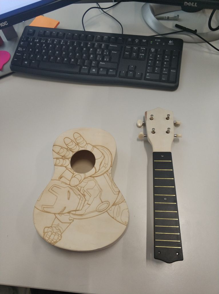
通过粘合固定桥接两个长螺钉位于车身中央位置。建议用铅笔在身体上标记正确的位置。我们将采用图像中标记的距离。
我们将在两个组件的并集处应用胶水。我们在拧紧螺丝的帮助下仔细固定这两个部件,直到接头干燥。我们将用1.5mm钻头为木头制作螺钉的两个孔。用两个长螺钉固定桥体。最后,我们将保护帽放在螺钉的头部。
步骤11:身体和颈部组装


为了组装这两个部分,我们在身体的头部有个洞,脖子上有两个突出部分。我们可以用胶水或热熔胶胶粘它们。为了获得更大的固定效果,您可以将音叉末端的孔连接到身体上。
步骤12:放入尤克里里琴弦


最后我们必须放置字符串,以便我们的仪器完成。
以前我们会将销的固定环插入穿过桅杆的突出部分中。为了放置琴弦,我们采用了套件附带的4个琴弦。首先,您必须区分每个字符串,因为它们并非完全相同。你必须绑住每根弦的一端(两个粗节用正常的结,两个薄的用一个双节)并将琴弦插入琴桥的插槽中。
然后我们将以下列方式放置字符串:
•第一个位置:G字符串(第二个最粗的字符串)。
•第二个位置:C字符串(粗字符串) )。
•第三个位置:E字符串(第二个较细的字符串)。
•第四个位置:一个字符串(较细的字符串)。
将字符串穿入孔中提供的插头。尝试通过在销上旋转两到三圈来固定每根绳子。在不施加过大力量的情况下拉紧琴弦并检查琴弦和琴鞍之间的距离。
如果你对如何制作它有任何疑问,你可以在教程中解释你如何正确地设置琴弦。
步骤13:测试


最后,我们要看看尤克里里琴是否有已正确组装,使第一个音品上的理想距离为0.1毫米,而第十二个音符上的理想距离约为1.2毫米。
需要调整四弦琴弦。我推荐你这个应用程序:GuitarTuna
-
led
+关注
关注
242文章
23278浏览量
660947
发布评论请先 登录
相关推荐
智能化灯光控制系统
开源项目!可以自主演奏音乐的尤克里里机器人!
舞台灯电机驱动芯片_步进驱动ic-选型指南_应用方案
STM32项目实战:基于STM32F4的智能灯光控制系统(LVGL),附项目教程/源码
LED灯光亮化引领着现代照明的潮流

如何给CyBootProgrammer.Img这个固件添加一条控制led状态的指令?
单通道直流LED灯光控制触摸芯片FS102WS规格说明书
FS102WS是一款用于 LED 灯光开关控制及亮度调节的触摸IC
麦爵士madrix智能灯光的应用趋势
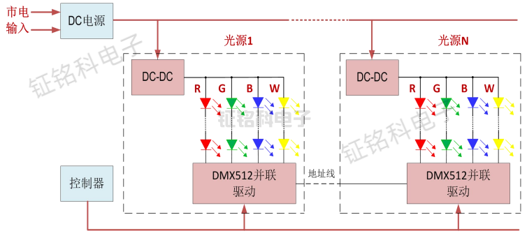
用于LED装饰照明DMX512并联驱动控制芯片作用与应用领域
LED城市景观亮化工程及驱动芯片SM18512PS的应用与优势


 如何给尤克里里琴添加LED灯光效果


评论