步骤1:了解算法

在DTMF中,每个符号根据图片上的表格使用两个频率进行编码。
该设备捕获麦克风的输入并计算八个频率的幅度。具有最大幅度的两个频率给出了编码符号的一行和一列。
数据采集
为了执行频谱分析,应以某个可预测的频率捕获样本。为了达到这个目的,我使用了具有最大精度的自由运行ADC模式(预分频器128),它提供了9615Hz的采样率。下面的代码显示了如何配置Arduino的ADC。
void initADC() {
// Init ADC; f = ( 16MHz/prescaler ) / 13 cycles/conversion
ADMUX = 0; // Channel sel, right-adj, use AREF pin
ADCSRA = _BV(ADEN) | // ADC enable
_BV(ADSC) | // ADC start
_BV(ADATE) | // Auto trigger
_BV(ADIE) | // Interrupt enable
_BV(ADPS2) | _BV(ADPS1) | _BV(ADPS0); // 128:1 / 13 = 9615 Hz
ADCSRB = 0; // Free-run mode
DIDR0 = _BV(0); // Turn off digital input for ADC pin
TIMSK0 = 0; // Timer0 off
}
And the interrupt handler looks like this
ISR(ADC_vect) {
uint16_t sample = ADC;samples[samplePos++] = sample - 400;
if(samplePos 》= N) {
ADCSRA &= ~_BV(ADIE); // Buffer full, interrupt off
}
}
频谱分析
收集样本后,我计算出8个频率的幅度,这些频率编码符号。我不需要为此运行完整的FFT,因此我使用了Goertzel的算法。
void goertzel(uint8_t *samples, float *spectrum) {
float v_0, v_1, v_2;
float re, im, amp;
for (uint8_t k = 0; k 《 IX_LEN; k++) {
float c = pgm_read_float(&(cos_t[k]));
float s = pgm_read_float(&(sin_t[k]));
float a = 2. * c;
v_0 = v_1 = v_2 = 0;
for (uint16_t i = 0; i 《 N; i++) {
v_0 = v_1;
v_1 = v_2;
v_2 = (float)(samples[i]) + a * v_1 - v_0;
}
re = c * v_2 - v_1;
im = s * v_2;
amp = sqrt(re * re + im * im);
spectrum[k] = amp;
}
}
步骤2:代码
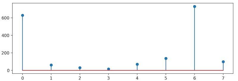
上图显示了数字3的编码示例,其中最大幅度对应于697Hz和1477Hz频率。
完整的草图如下
/**
* Connections:
* [ Mic to Arduino ]
* - Out -》 A0
* - Vcc -》 3.3V
* - Gnd -》 Gnd
* - Arduino: AREF -》 3.3V
* [ Display to Arduino ]
* - Vcc -》 5V
* - Gnd -》 Gnd
* - DIN -》 D11
* - CLK -》 D13
* - CS -》 D9
*/
#include
#include
#include
#define CS_PIN 9
#define N 256
#define IX_LEN 8
#define THRESHOLD 20
LEDMatrixDriver lmd(1, CS_PIN);
uint8_t samples[N];
volatile uint16_t samplePos = 0;
float spectrum[IX_LEN];
// Frequences [697.0, 770.0, 852.0, 941.0, 1209.0, 1336.0, 1477.0, 1633.0]
// Calculated for 9615Hz 256 samples
const float cos_t[IX_LEN] PROGMEM = {
0.8932243011955153, 0.8700869911087115, 0.8448535652497071, 0.8032075314806449,
0.6895405447370669, 0.6343932841636456, 0.5555702330196023, 0.4713967368259978
};
const float sin_t[IX_LEN] PROGMEM = {
0.44961132965460654, 0.49289819222978404, 0.5349976198870972, 0.5956993044924334,
0.7242470829514669, 0.7730104533627369, 0.8314696123025451, 0.8819212643483549
};
typedef struct {
char digit;
uint8_t index;
} digit_t;
digit_t detected_digit;
const char table[4][4] PROGMEM = {
{‘1’, ‘2’, ‘3’, ‘A’},
{‘4’, ‘5’, ‘6’, ‘B’},
{‘7’, ‘8’, ‘9’, ‘C’},
{‘*’, ‘0’, ‘#’, ‘D’}
};
const uint8_t char_indexes[4][4] PROGMEM = {
{1, 2, 3, 10},
{4, 5, 6, 11},
{7, 8, 9, 12},
{15, 0, 14, 13}
};
byte font[16][8] = {
{0x00,0x38,0x44,0x4c,0x54,0x64,0x44,0x38}, // 0
{0x04,0x0c,0x14,0x24,0x04,0x04,0x04,0x04}, // 1
{0x00,0x30,0x48,0x04,0x04,0x38,0x40,0x7c}, // 2
{0x00,0x38,0x04,0x04,0x18,0x04,0x44,0x38}, // 3
{0x00,0x04,0x0c,0x14,0x24,0x7e,0x04,0x04}, // 4
{0x00,0x7c,0x40,0x40,0x78,0x04,0x04,0x38}, // 5
{0x00,0x38,0x40,0x40,0x78,0x44,0x44,0x38}, // 6
{0x00,0x7c,0x04,0x04,0x08,0x08,0x10,0x10}, // 7
{0x00,0x3c,0x44,0x44,0x38,0x44,0x44,0x78}, // 8
{0x00,0x38,0x44,0x44,0x3c,0x04,0x04,0x78}, // 9
{0x00,0x1c,0x22,0x42,0x42,0x7e,0x42,0x42}, // A
{0x00,0x78,0x44,0x44,0x78,0x44,0x44,0x7c}, // B
{0x00,0x3c,0x44,0x40,0x40,0x40,0x44,0x7c}, // C
{0x00,0x7c,0x42,0x42,0x42,0x42,0x44,0x78}, // D
{0x00,0x0a,0x7f,0x14,0x28,0xfe,0x50,0x00}, // #
{0x00,0x10,0x54,0x38,0x10,0x38,0x54,0x10} // *
};
void initADC() {
// Init ADC; f = ( 16MHz/prescaler ) / 13 cycles/conversion
ADMUX = 0; // Channel sel, right-adj, use AREF pin
ADCSRA = _BV(ADEN) | // ADC enable
_BV(ADSC) | // ADC start
_BV(ADATE) | // Auto trigger
_BV(ADIE) | // Interrupt enable
_BV(ADPS2) | _BV(ADPS1) | _BV(ADPS0); // 128:1 / 13 = 9615 Hz
ADCSRB = 0; // Free-run mode
DIDR0 = _BV(0); // Turn off digital input for ADC pin
TIMSK0 = 0; // Timer0 off
}
void goertzel(uint8_t *samples, float *spectrum) {
float v_0, v_1, v_2;
float re, im, amp;
for (uint8_t k = 0; k 《 IX_LEN; k++) {
float c = pgm_read_float(&(cos_t[k]));
float s = pgm_read_float(&(sin_t[k]));
float a = 2. * c;
v_0 = v_1 = v_2 = 0;
for (uint16_t i = 0; i 《 N; i++) {
v_0 = v_1;
v_1 = v_2;
v_2 = (float)(samples[i]) + a * v_1 - v_0;
}
re = c * v_2 - v_1;
im = s * v_2;
amp = sqrt(re * re + im * im);
spectrum[k] = amp;
}
}
float avg(float *a, uint16_t len) {
float result = .0;
for (uint16_t i = 0; i 《 len; i++) {
result += a[i];
}
return result / len;
}
int8_t get_single_index_above_threshold(float *a, uint16_t len, float threshold) {
if (threshold 《 THRESHOLD) {
return -1;
}
int8_t ix = -1;
for (uint16_t i = 0; i 《 len; i++) {
if (a[i] 》 threshold) {
if (ix == -1) {
ix = i;
} else {
return -1;
}
}
}
return ix;
}
void detect_digit(float *spectrum) {
float avg_row = avg(spectrum, 4);
float avg_col = avg(&spectrum[4], 4);
int8_t row = get_single_index_above_threshold(spectrum, 4, avg_row);
int8_t col = get_single_index_above_threshold(&spectrum[4], 4, avg_col);
if (row != -1 && col != -1 && avg_col 》 200) {
detected_digit.digit = pgm_read_byte(&(table[row][col]));
detected_digit.index = pgm_read_byte(&(char_indexes[row][col]));
} else {
detected_digit.digit = 0;
}
}
void drawSprite(byte* sprite) {
// The mask is used to get the column bit from the sprite row
byte mask = B10000000;
for(int iy = 0; iy 《 8; iy++ ) {
for(int ix = 0; ix 《 8; ix++ ) {
lmd.setPixel(7 - iy, ix, (bool)(sprite[iy] & mask ));
// shift the mask by one pixel to the right
mask = mask 》》 1;
}
// reset column mask
mask = B10000000;
}
}
void setup() {
cli();
initADC();
sei();
Serial.begin(115200);
lmd.setEnabled(true);
lmd.setIntensity(2);
lmd.clear();
lmd.display();
detected_digit.digit = 0;
}
unsigned long z = 0;
void loop() {
while(ADCSRA & _BV(ADIE)); // Wait for audio sampling to finish
goertzel(samples, spectrum);
detect_digit(spectrum);
if (detected_digit.digit != 0) {
drawSprite(font[detected_digit.index]);
lmd.display();
}
if (z % 5 == 0) {
for (int i = 0; i 《 IX_LEN; i++) {
Serial.print(spectrum[i]);
Serial.print(“ ”);
}
Serial.println();
Serial.println((int)detected_digit.digit);
}
z++;
samplePos = 0;
ADCSRA |= _BV(ADIE); // Resume sampling interrupt
}
ISR(ADC_vect) {
uint16_t sample = ADC;
samples[samplePos++] = sample - 400;
if(samplePos 》= N) {
ADCSRA &= ~_BV(ADIE); // Buffer full, interrupt off
}
}
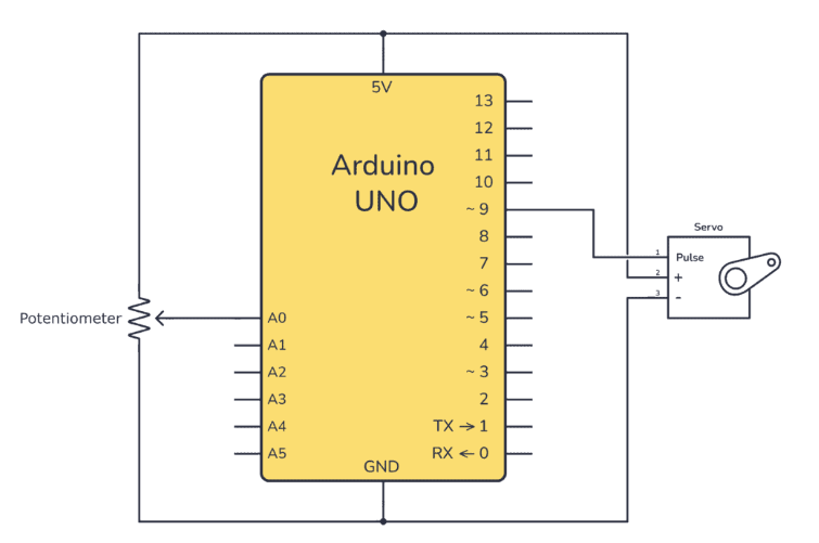
步骤3:原理图
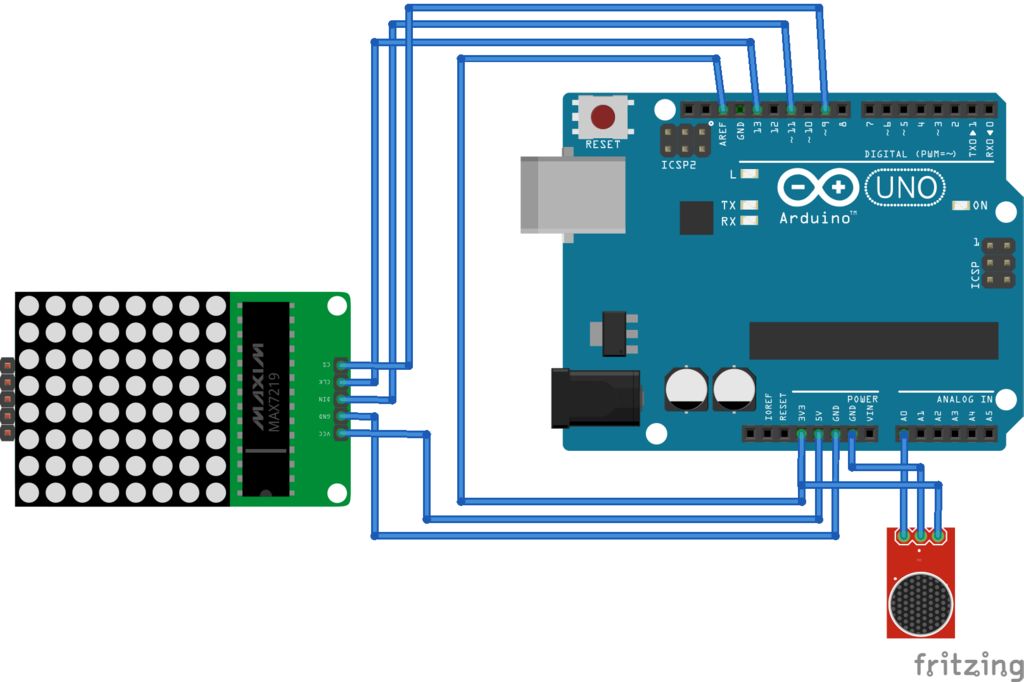
应进行以下连接:
麦克风与Arduino
Out -》 A0
Vcc -》 3.3V
Gnd -》 Gnd
将AREF连接到3.3V很重要。
显示到Arduino
Vcc -》 5V
Gnd -》 Gnd
DIN -》 D11
CLK -》 D13
CS -》 D9
步骤4:结论
这里可以改进什么?我以9615Hz的速率使用N = 256个样本,该速率有一些频谱泄漏,如果N = 205且速率为8000Hz,则所需频率与离散化网格重合。对于该ADC,应在定时器溢出模式下使用。
责任编辑:wv
-
解码器
+关注
关注
9文章
1142浏览量
40713 -
DTMF
+关注
关注
1文章
74浏览量
47081 -
Arduino
+关注
关注
188文章
6468浏览量
186920
发布评论请先 登录
相关推荐
无线网解码器怎么连接
无线解码器的质量标准是什么
解码器和控制器区别是什么
控制器解码器的使用方法
全景声解码器

为什么好的播放器还要配解码器
9740解码器配什么光栅
光栅解码器损坏的表现有哪些
超低功耗立体声编解码器Arduino评估板ARD-AUDIO-DA7212数据手册
音视频解码器硬件加速:实现更流畅的播放效果


 如何用Arduino UNO实现DTMF解码器



评论