简介
这实际上不是任何产品或公共项目(!)-它是我设计用来帮助我评估太阳能电池板以及它们在何时工作的方式的给电池充电。通常,这需要大量的万用表,如果您必须不断更换面板,这会有些麻烦。因此,我决定建立一个可以帮助我的专业工具。这就是我想要的!
可携带!很难测试内部的太阳能电池板
能够登录到SD卡进行长期数据分析(稍后添加)
保持太阳能电池板电压的跟踪
》
保持电池电压
保持流经面板到充电器的电流量
我想过是否必须构建此电池,有人可能会觉得我的笔记有用。但是,本文档的主要目的是演示如何使用adafruit商店中随附的机柜。

此设计适用于〜6V面板,单个锂聚合物电池和充电器。它可以很容易地适应任何类型的面板和充电器,您只需要调整电阻分压器等等!
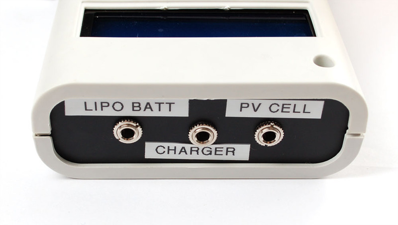
请注意,该项目不是太阳能数据记录器。您确实需要使用电池为它供电,这仅用于分析面板!
零件列表
Arduino,外壳和显示器:
Adafruit Metro 328P(与Arduino Uno兼容)
Arduino的外壳
16x2 LCD
0.1“接头和电位计与LCD配套使用,如果您从Adafruit商店购买,则包括在内
数据记录屏蔽或原型屏蔽(在本教程中我们实际上并未进行任何数据记录,因此,如果您只想查看而不跟踪,则原型屏蔽就可以了。)
高级母跳线(您也可以只需使用普通线,但我们希望能够轻松拆卸LCD。)
模拟电子设备!
3 x 10K电阻器
1 x 47K电阻
1 x 15K电阻
1 x 1.0K电阻
3 x 3.5mm接线端子
0.1 ohm(电流检测)电阻器
8引脚DIP双轨至轨输入/输出运算放大器(TS922正常工作)
用于运算放大器的8引脚DIP插座
3 x单声道3.5毫米唱机插孔
3 x单声道3.5毫米唱机插头
然后,当然是要记录的东西。您可以替代其他类型的电池和充电器。
6V 1W太阳能电池板
Lipoly充电器
锂聚合物电池
如果要将它带到外面,则需要便携式电源,我们喜欢AA的电源,但是如果不打算长时间使用,也可以使用9V。
6 x AA电池座
带开关的9V座
9V电池夹
模拟物
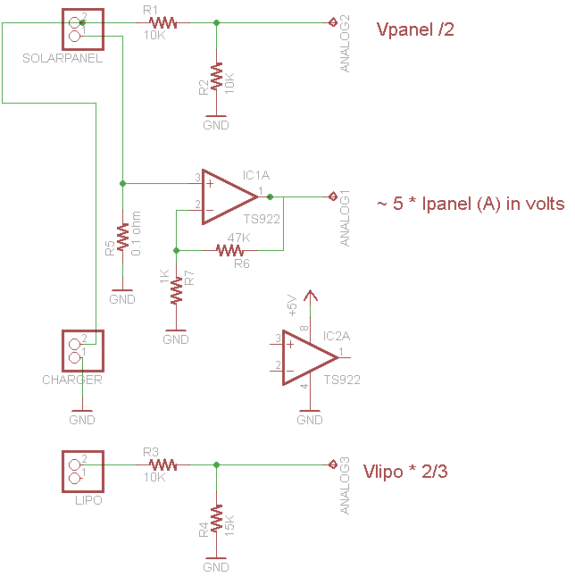
有一些模拟的东西。最容易理解的两个部分是由 R1 和 R2 和 R3 和 R4 制成的分压器。 R1 和 R2 取6V太阳能电池板电压并将其除以2(只需使R1 = R2),以使模拟转换器的输入低于3.3V。同样, R3 和 R4 采用高达4.2V的限制电压并将其除以3/5,以使其降至3.3V以下,因此我们可以跟踪该电压
更复杂的部分是用于测量电流消耗的运算放大器。我们在太阳能电池板的负极线和地面之间插入一个0.1欧姆的电阻,这样我们就可以通过测量跨过电阻的电流来测量流过电池板的电流。 1 A的电流变为100mV(我们的面板的电流不能超过300mA,也就是30mV)。足够低,不会影响太阳能电池板的充电能力。但是,30mV确实很低,这是我们期望的面板最大值。我们使用同相放大器将电压放大到更大且更易于管理。特别是。该放大器将电压乘以 1 + R6/R7 = 48x!这会将我们的30mV最大信号变为1.5V。我们不进行更多放大的原因是,我希望能够使用更大的面板,该面板可以提供500mA或更高的电流,因此会有一些裕量。
通常,我使用的电阻器在我的桌子上(0.1欧姆除外,这个值很重要),因此请随时调整这些值。
如果我今天要构建此项目,则应使用合适的高端电流传感器,例如精确的INA219,可以测量高压,并且易于使用!
可悲的是,当我最初设计此项目时,它并不在手边
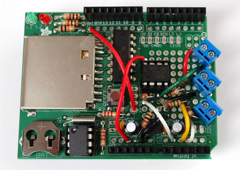
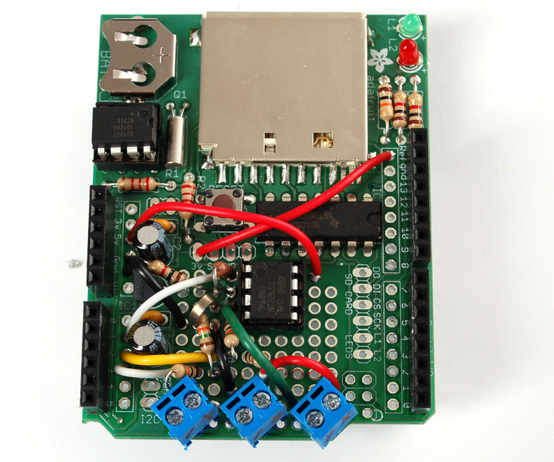
现在可以使用烙铁了!这实际上是最烦人的部分。如果您不需要数据记录-仅需LCD反馈,则将其焊接到Protoshield上会感到更加高兴,因为有更多的空间。单击图片以放大照片。要进行焊接,我们在导线上弯曲并在钳夹之前仔细焊接在一起。有时很难遵循,所以要慢慢检查每一步的工作。
请注意,我们将 ARef 绑定到3.3v以获得更稳定的模拟读数-特别是在使用电池时动力的便携式记录仪!

套管
我将从准备案件开始。对于底部,将部件咬合起来以覆盖两个孔。
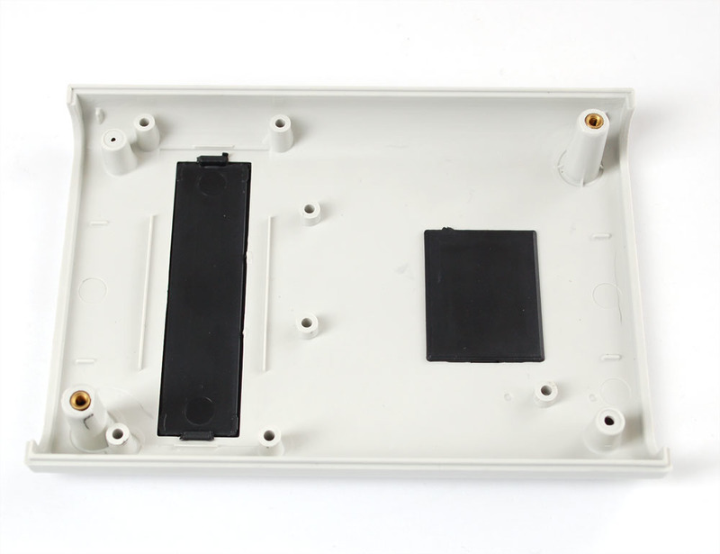
放置Arduino,使其与安装孔对齐。
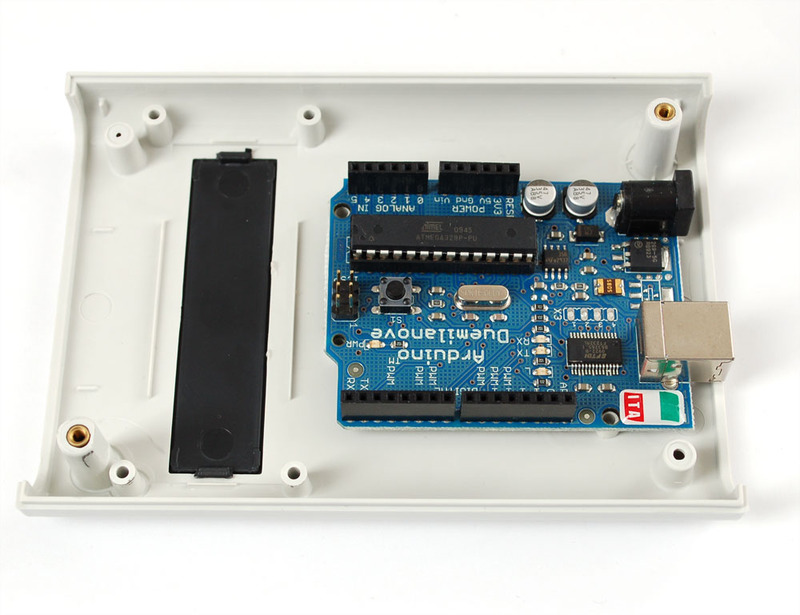
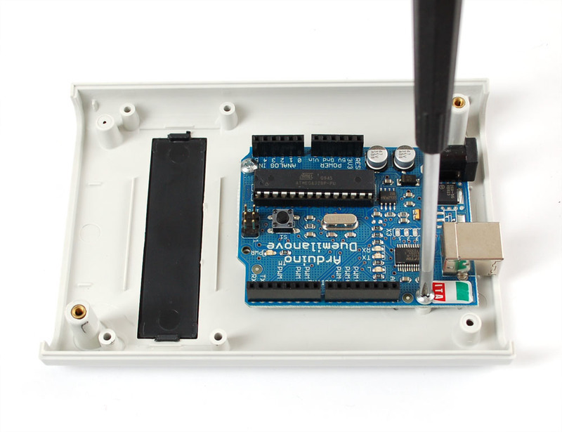
附加!使用两个螺钉,第三个螺钉不合适,因为Arduino钻头太小。
LCD
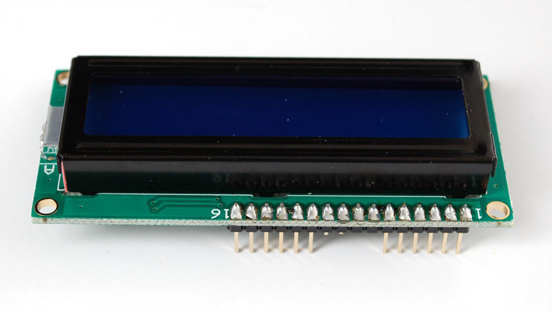
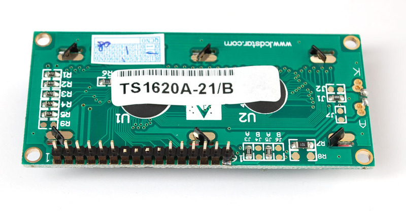
从包装中取出LCD。您将需要某种10K电位器。我们将使用一些插头和高级插座跳线,但您可以跳过该部分而仅焊接直接导线。

将标头焊接进去,然后裁剪未使用的数据引脚以避免混淆。
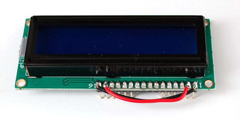
将LED背光灯线连接到LCD逻辑电源线。
接地RW引脚(未使用)。
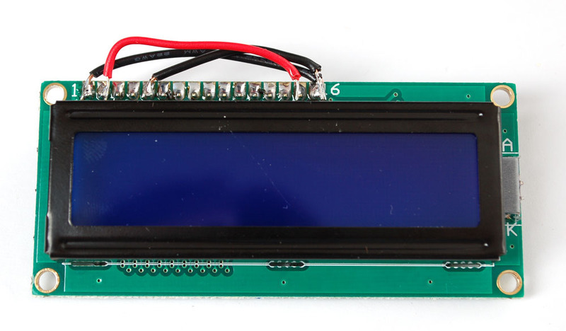
并除去该引脚以及引脚#1和#2(它们靠近安装柱,因此我们将进行连接而不是针脚#15和#16)。
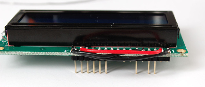
将10K电位器连接到5V,引脚3和接地。
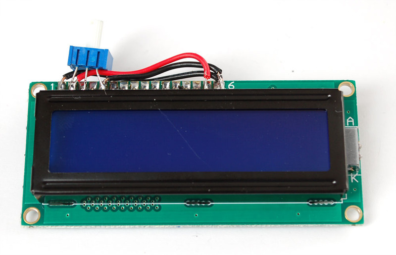
和固定销3。
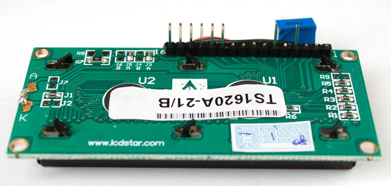
现在,我们有从左到右使用的8个引脚:接地,电源,D7至D4,RS和EN。连接套接字。
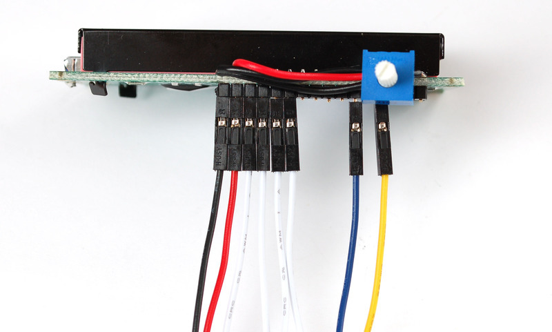
并剪裁
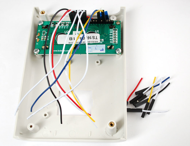
LCD连接和测试
从接通电源开始,红色变为+ 5V,黑色变为接地。在LCD教程中执行测试以验证对比度电位计是否正常工作。
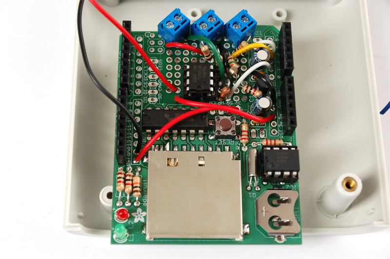
这样连接其余电线:
EN→数字#2
RS→数字#3
D4→数字#4
D5→数字#5
D6→数字#6
D7→数字#7
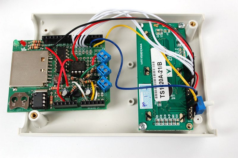
然后尝试通过上传草图将其显示出来。即使它什么也不显示,您也应该使LCD正常工作。


下载:Project Zip 或 solartrack.ino | 在Github上查看
复制代码
/*
Portable solar panel efficiency tracker. For testing out solar panels!
See https://learn.adafruit.com/portable-solar-charging-tracker for more information
Code is public domain, MIT License by Limor “Ladyada” Fried
*/
// include the library code:
#include
#include
// initialize the library with the numbers of the interface pins
LiquidCrystal lcd(2, 3, 4, 5, 6, 7 );
#define aref_voltage 3.3 // we tie 3.3V to ARef and measure it with a multimeter!
int lipoPin = 3; // the battery
float lipoMult = 1.666; // how much to multiply to get the original voltage
int PVPin = 2; // the cell
float PVMult = 2; // how much to multiply to get the original voltage
int currentPin = 1;
float currentMult = 208; // how much to multiply to get the original current draw
void setup(void) {
// We‘ll send debugging information via the Serial monitor
Serial.begin(9600);
// set up the LCD’s number of rows and columns:
lcd.begin(16, 2);
lcd.clear();
// Print a message to the LCD.
lcd.print(“Solar logger”);
delay(2000);
lcd.clear();
// If you want to set the aref to something other than 5v
analogReference(EXTERNAL);
byte delta[8] = {
B00000,
B00100,
B00100,
B01010,
B01010,
B10001,
B11111,
B00000
};
lcd.createChar(0, delta);
}
void loop(void) {
adcreading = analogRead(lipoPin);
Serial.println(adcreading);
float lipoV = adcreading;
lipoV *= aref_voltage;
lipoV /= 1024;
lipoV *= lipoMult;
lcd.clear();
Serial.print(“LiPo voltage = ”);
Serial.println(lipoV); // the raw analog reading
lcd.setCursor(0, 0);
lcd.print(“LiPo=”);
lcd.print(lipoV);
lcd.print(‘ ’);
lcd.write((uint8_t)0);
adcreading = analogRead(PVPin);
float PVV = adcreading;
PVV *= aref_voltage;
PVV /= 1024;
PVV *= PVMult;
lcd.print((int)((PVV-lipoV) * 1000), DEC); // in mV
lcd.print(“mV”);
Serial.print(“PV voltage = ”);
Serial.println(PVV); // the raw analog reading
lcd.setCursor(0, 1);
lcd.print(“PV=”);
lcd.print(PVV);
adcreading = analogRead(currentPin);
float currentI = adcreading;
currentI *= aref_voltage;
currentI /= 1024;
currentI *= currentMult;
Serial.print(“Current (mA) = ”);
Serial.println(currentI); // the raw analog reading
lcd.print(“ I=”);
lcd.print((int)currentI);
lcd.print(“mA”);
delay(1000);
}
/*
Portable solar panel efficiency tracker. For testing out solar panels!
See https://learn.adafruit.com/portable-solar-charging-tracker for more information
Code is public domain, MIT License by Limor “Ladyada” Fried
*/
// include the library code:
#include
#include
// initialize the library with the numbers of the interface pins
LiquidCrystal lcd(2, 3, 4, 5, 6, 7 );
#define aref_voltage 3.3 // we tie 3.3V to ARef and measure it with a multimeter!
int lipoPin = 3; // the battery
float lipoMult = 1.666; // how much to multiply to get the original voltage
int PVPin = 2; // the cell
float PVMult = 2; // how much to multiply to get the original voltage
int currentPin = 1;
float currentMult = 208; // how much to multiply to get the original current draw
void setup(void) {
// We‘ll send debugging information via the Serial monitor
Serial.begin(9600);
// set up the LCD’s number of rows and columns:
lcd.begin(16, 2);
lcd.clear();
// Print a message to the LCD.
lcd.print(“Solar logger”);
delay(2000);
lcd.clear();
// If you want to set the aref to something other than 5v
analogReference(EXTERNAL);
byte delta[8] = {
B00000,
B00100,
B00100,
B01010,
B01010,
B10001,
B11111,
B00000
};
lcd.createChar(0, delta);
}
void loop(void) {
int adcreading;
adcreading = analogRead(lipoPin);
Serial.println(adcreading);
float lipoV = adcreading;
lipoV *= aref_voltage;
lipoV /= 1024;
lipoV *= lipoMult;
lcd.clear();
Serial.print(“LiPo voltage = ”);
Serial.println(lipoV); // the raw analog reading
lcd.setCursor(0, 0);
lcd.print(“LiPo=”);
lcd.print(lipoV);
lcd.print(‘ ’);
lcd.write((uint8_t)0);
adcreading = analogRead(PVPin);
float PVV = adcreading;
PVV *= aref_voltage;
PVV /= 1024;
PVV *= PVMult;
lcd.print((int)((PVV-lipoV) * 1000), DEC); // in mV
lcd.print(“mV”);
Serial.print(“PV voltage = ”);
Serial.println(PVV); // the raw analog reading
lcd.setCursor(0, 1);
lcd.print(“PV=”);
lcd.print(PVV);
adcreading = analogRead(currentPin);
float currentI = adcreading;
currentI *= aref_voltage;
currentI /= 1024;
currentI *= currentMult;
Serial.print(“Current (mA) = ”);
Serial.println(currentI); // the raw analog reading
lcd.print(“ I=”);
lcd.print((int)currentI);
lcd.print(“mA”);
delay(1000);
}
现在可以连接外部面板和电池等。接线端子还可以,但不是很优雅。相反,我将使用可插拔连接器。音频连接器在这里可以很好地工作,每个连接只需要2个引脚(接地和信号),因此3.5毫米单声道耳机插头和插孔是一种廉价且易于获得的解决方案。一定要获得面板安装插孔!
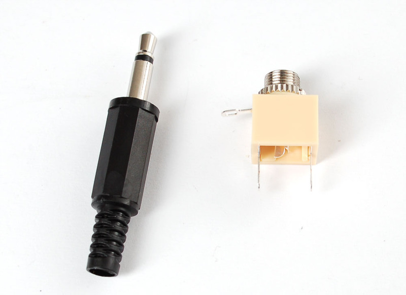
从连接充电器输出的JST电缆开始(以测量脂质)。松开插头,穿过电线,然后将每个引脚焊接到压接处。通常,您应始终使“套管”或“环”接地,并向“尖端”发出正信号。保持事物易于跟踪!
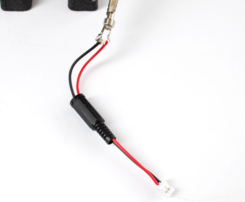
压接,确保不使电线短路。这可能有点挑战,因此请使用万用表进行测试!
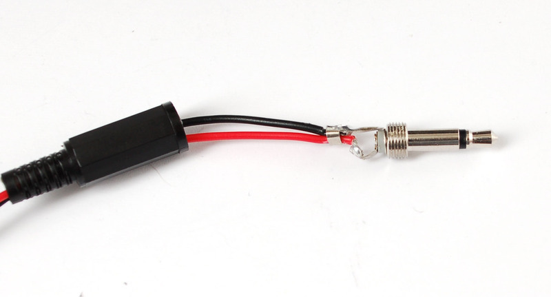
下一步,剥去miniB usb电缆,并拔出红色和黑色电线。我们还使用一些热缩来保护电缆的末端。
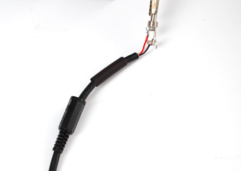
压接
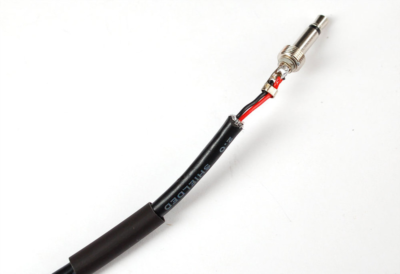
热缩!
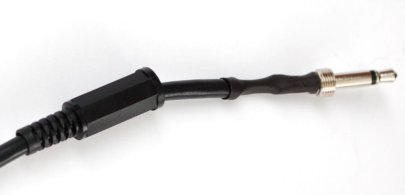
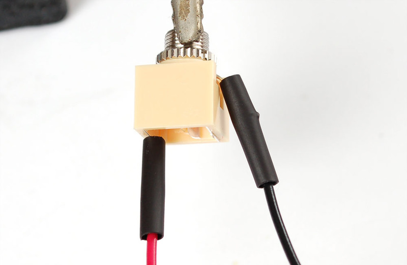
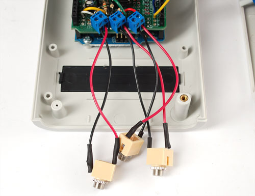
接下来是千斤顶。如图所示,将任何绞合线连接到套管和末端连接。
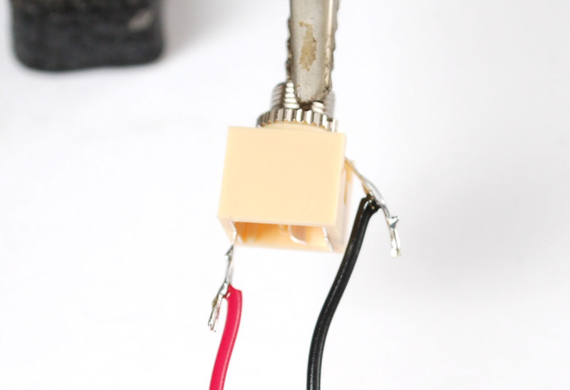
我们喜欢热收缩!
将插孔连接到端子块。
在完成所有步骤之前,现在是测试的好时机!确认从面板和锂聚合物电池获得了合理的电压。如果您可以靠近窗户,请查看是否可以给电池充电。
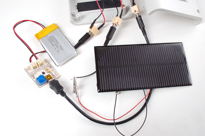
完成
当然,我们希望将面板安装插孔安装在面板上。抓住盒子的末端。它是由ABS制成的。
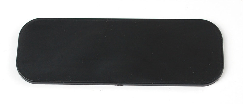
意味着它们非常容易钻孔或加工!
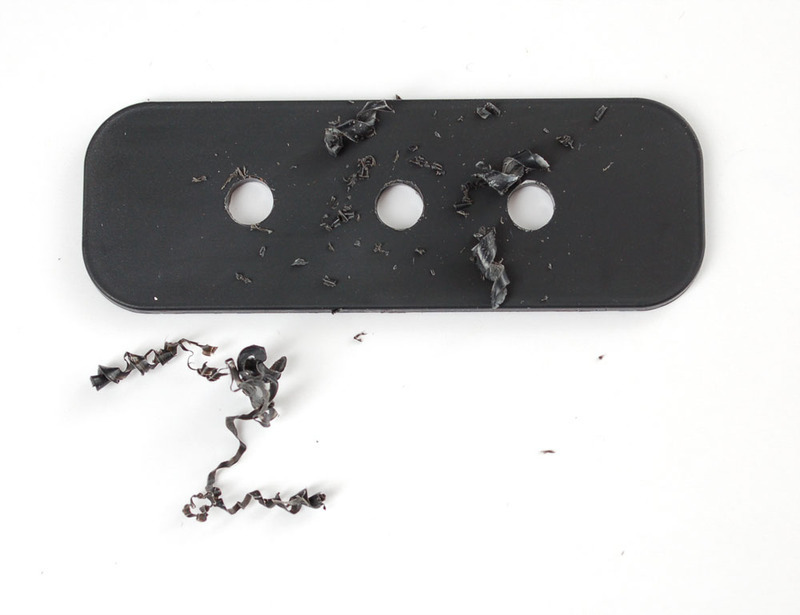
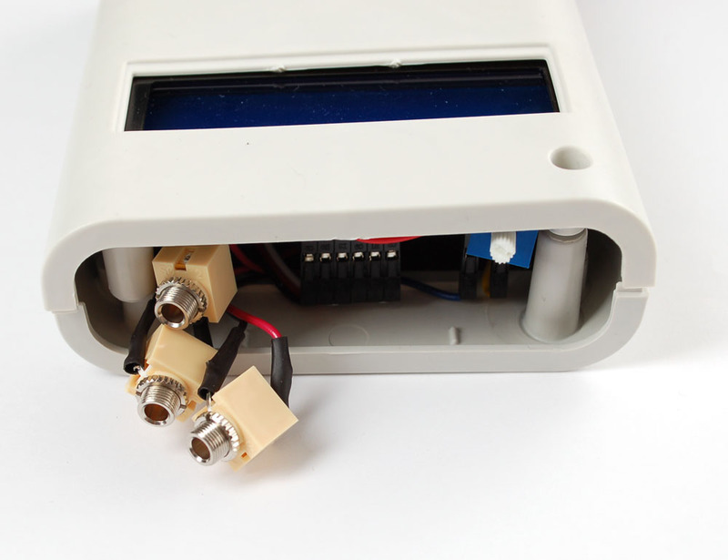
我们有一个标签制造商,所以我们做了漂亮的小标签!
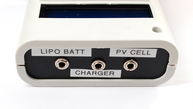
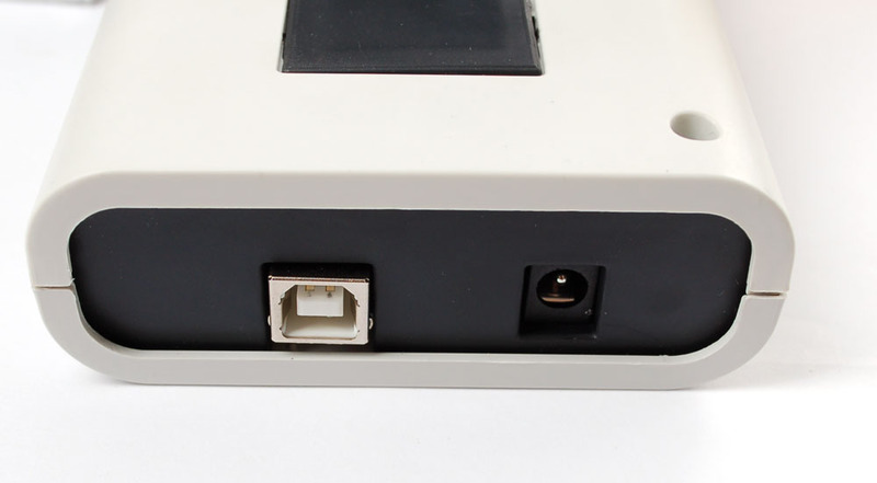
另一个一侧获得了覆盖Arduino电源和编程插槽的预切盒。
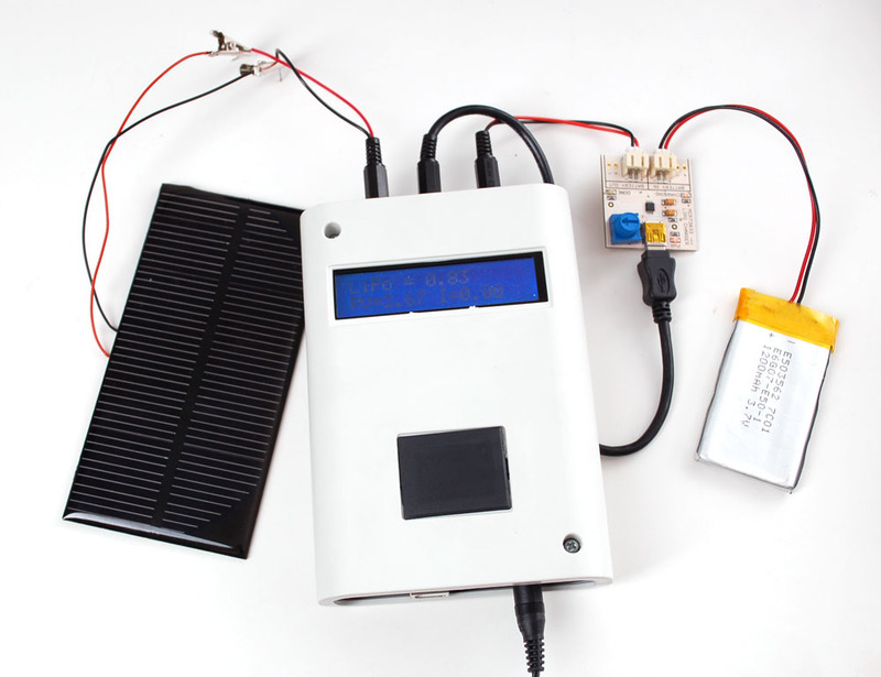
准备出发!在这里,我展示了如何通过连接鳄鱼皮来尝试不同的面板。脂质输入来自充电器上的直通连接。当面板为电池充电时,我可以跟踪电压和电流。
责任编辑:wv
-
太阳能
+关注
关注
37文章
3405浏览量
114186 -
追踪器
+关注
关注
0文章
171浏览量
25698
发布评论请先 登录
相关推荐
便携式储能已经实现全国产了吗?
便携式示波器的技术原理和应用场景
实现高效供电,PMU成便携式储能中的关键
GoSun推出电动汽车太阳能充电盒
太阳能组件el测试仪的便携款版本有哪些特点?
太阳能充电器的原理图


 便携式太阳能充电追踪器的制作



评论