本文来源电子发烧友社区,作者:马先生, 帖子地址:https://bbs.elecfans.com/jishu_2299040_1_1.html
有幸成功申请到了武汉芯源CW32F003FXSTARTKI开发板。
首先第一步阅读对应的手册。
其中有一条阐述了ISP下载
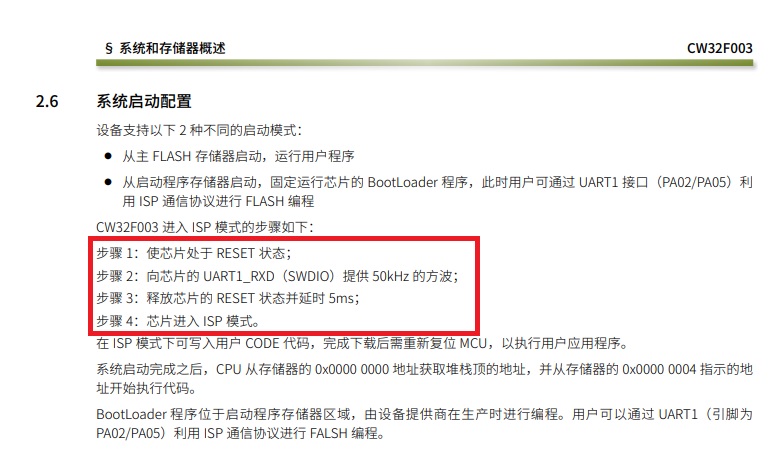
接下来我们从官网上下载一个对应的下载工具
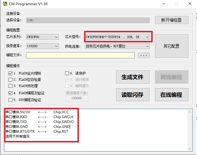
1.选择串口
2.选择芯片
3.选择对应程序
4.按照下方大的红色方框连线
连接串口和下载口的部分
其中ch340的电源也是要接的。
5.点击在线编程。
////////////////////////////////////////////////////////////////////////////////////////////////////////////////////////////
#define Set_CS PA00_SETHIGH() //设置CS0位高电平
#define Reset_CS PA00_SETLOW() //设置CS0位低电平
#define SetR_S PA01_SETHIGH() //设置RS(A0)位高电平
#define Reset_R_S PA01_SETLOW() //设置RS(A0)位低电平
#define Set_RES PA02_SETHIGH() //设置RES位高电平
#define Reset_RES PA02_SETLOW() //设置RES位高电平
#define Set_SCK PA03_SETHIGH() //设置SCLK位高电平
#define Reset_SCK PA03_SETLOW() //设置SCLK位低电平
#define Set_SDA PA05_SETHIGH() //设置SDA位高电平
#define Reset_SDA PA05_SETLOW() //设置SDA位低电平
unsigned char s0[42][16]=
{
/*--文字:0--*/
/*--宋体12;此字体下对应的点阵为:宽x高=8x16 --*/
0x00,0xE0,0x10,0x08,0x08,0x10,0xE0,0x00,0x00,0x0F,0x10,0x20,0x20,0x10,0x0F,0x00,
/*--文字:1--*/
/*--宋体12;此字体下对应的点阵为:宽x高=8x16 --*/
0x00,0x10,0x10,0xF8,0x00,0x00,0x00,0x00,0x00,0x20,0x20,0x3F,0x20,0x20,0x00,0x00,
/*--文字:2--*/
/*--宋体12;此字体下对应的点阵为:宽x高=8x16 --*/
0x00,0x70,0x08,0x08,0x08,0x88,0x70,0x00,0x00,0x30,0x28,0x24,0x22,0x21,0x30,0x00,
/*--文字:3--*/
/*--宋体12;此字体下对应的点阵为:宽x高=8x16 --*/
0x00,0x30,0x08,0x88,0x88,0x48,0x30,0x00,0x00,0x18,0x20,0x20,0x20,0x11,0x0E,0x00,
/*--文字:4--*/
/*--宋体12;此字体下对应的点阵为:宽x高=8x16 --*/
0x00,0x00,0xC0,0x20,0x10,0xF8,0x00,0x00,0x00,0x07,0x04,0x24,0x24,0x3F,0x24,0x00,
/*--文字:5--*/
/*--宋体12;此字体下对应的点阵为:宽x高=8x16 --*/
0x00,0xF8,0x08,0x88,0x88,0x08,0x08,0x00,0x00,0x19,0x21,0x20,0x20,0x11,0x0E,0x00,
/*--文字:6--*/
/*--宋体12;此字体下对应的点阵为:宽x高=8x16 --*/
0x00,0xE0,0x10,0x88,0x88,0x18,0x00,0x00,0x00,0x0F,0x11,0x20,0x20,0x11,0x0E,0x00,
/*--文字:7--*/
/*--宋体12;此字体下对应的点阵为:宽x高=8x16 --*/
0x00,0x38,0x08,0x08,0xC8,0x38,0x08,0x00,0x00,0x00,0x00,0x3F,0x00,0x00,0x00,0x00,
/*--文字:8--*/
/*--宋体12;此字体下对应的点阵为:宽x高=8x16 --*/
0x00,0x70,0x88,0x08,0x08,0x88,0x70,0x00,0x00,0x1C,0x22,0x21,0x21,0x22,0x1C,0x00,
/*--文字:9--*/
/*--宋体12;此字体下对应的点阵为:宽x高=8x16 --*/
0x00,0xE0,0x10,0x08,0x08,0x10,0xE0,0x00,0x00,0x00,0x31,0x22,0x22,0x11,0x0F,0x00,
/*--文字::10--*/
/*--宋体12;此字体下对应的点阵为:宽x高=8x16 --*/
0x00,0x00,0x00,0xC0,0xC0,0x00,0x00,0x00,0x00,0x00,0x00,0x18,0x18,0x00,0x00,0x00,
/*--文字:小点 11 --*/
/*--宋体12;此字体下对应的点阵为:宽x高=8x16 --*/
0x00,0x00,0x00,0x00,0x00,0x00,0x00,0x00,0x00,0x30,0x30,0x00,0x00,0x00,0x00,0x00,
/*--调入了一幅图像:大点 12--*/
/*--宽度x高度=8x16--*/
0x00,0x00,0x00,0x00,0x00,0x00,0x00,0x00,0x00,0x00,0x78,0x78,0x78,0x78,0x00,0x00,
};
/******************************************************************************
* Local pre-processor symbols/macros ('#define')
******************************************************************************/
/******************************************************************************
* Global variable definitions (declared in header file with 'extern')
******************************************************************************/
/******************************************************************************
* Local type definitions ('typedef')
******************************************************************************/
/******************************************************************************
* Local function prototypes ('static')
******************************************************************************/
void RCC_Configuration(void);
void GPIO_Configuration(void);
void NVIC_Configuration(void);
void RTC_Configuration(void);
void ADC_Configuration(void);
void Sleep_Configuration(void);
void delay(uint16_t ms);
void RTC_IRQHandlerCallBack(void);
void LCD_GPIO_Config(void);
void initial_lcd(void);
void WRITE_STRING(unsigned char plat, unsigned char column, unsigned char p, unsigned char c);
/******************************************************************************
* Local variable definitions ('static') *
******************************************************************************/
uint32_t flag=0;
/******************************************************************************
* Local pre-processor symbols/macros ('#define')
******************************************************************************/
/*****************************************************************************
* Function implementation - global ('extern') and local ('static')
******************************************************************************/
/**
******************************************************************************
** briefMain function of project
**
** return uint32_t return value, if needed
**
** This sample toggle GPIOA.00
**
******************************************************************************/
/**
* @briefRTC时钟测试,初始化日历,使用间隔中断0.5秒通过Log输出日期时间
* @return int32_t
*/
int32_t main(void)
{
uint32_t cnt;
/* System Clocks Configuration */
RCC_Configuration();
/* GPIO Configuration */
GPIO_Configuration();
RTC_Configuration();
ADC_Configuration();
Sleep_Configuration();
/* NVIC Configuration */
NVIC_Configuration();
LCD_GPIO_Config();
initial_lcd();
while(1)
{
WRITE_STRING(1,1,1,0);
}
}
/**
* @briefConfigures the different system clocks.
* @paramNone
* @retval None
*/
void RCC_Configuration(void)
{
RCC_HSI_Enable(RCC_HSIOSC_DIV6); // 8MHz主频
RCC_LSI_Enable(); // 内部低速时钟作为RTC时钟源,精度较差
// 如需要RTC走时精度高,需要使用外部高精度晶体作为时钟源
// RCC_LSE_Enable(RCC_LSE_MODE_OSC, RCC_LSE_AMP_NORMAL, RCC_LSE_DRIVER_NORMAL);
RCC_APBPeriphClk_Enable1(RCC_APB1_PERIPH_RTC, ENABLE);
}
/**
* @briefConfigure the GPIO Pins.
* @paramNone
* @retval None
*/
void GPIO_Configuration(void)
{
// PA4 PB4唤醒
GPIO_InitTypeDef GPIO_InitStructure = {0};
GPIO_InitStructure.IT = GPIO_IT_FALLING |GPIO_IT_RISING; // 双沿触发中断
GPIO_InitStructure.Mode = GPIO_MODE_INPUT_PULLUP; // 输入上拉
GPIO_InitStructure.Pins = GPIO_PIN_4;
__RCC_GPIOA_CLK_ENABLE(); // 开GPIOA模块的时钟
__RCC_GPIOB_CLK_ENABLE(); // 开GPIOB模块的时钟
GPIO_Init(CW_GPIOA, &GPIO_InitStructure);
GPIO_Init(CW_GPIOB, &GPIO_InitStructure);
GPIO_ConfigFilter(CW_GPIOA, GPIO_PIN_4, GPIO_FLTCLK_LSI); // 休眠时,中断唤醒通过LSI时钟去抖动。
GPIO_ConfigFilter(CW_GPIOB, GPIO_PIN_4, GPIO_FLTCLK_LSI);
CW_GPIOA->ICR = 0x0000;
CW_GPIOB->ICR = 0x0000; // 清中断标志
GPIO_InitStructure.IT = GPIO_IT_NONE;
GPIO_InitStructure.Mode = GPIO_MODE_OUTPUT_PP;
GPIO_InitStructure.Pins = GPIO_PIN_8 | GPIO_PIN_9;
GPIO_Init(CW_GPIOB, &GPIO_InitStructure);
PB08_SETLOW();
PB09_SETHIGH();
}
void RTC_Configuration(void)
{
RTC_InitTypeDef RTC_InitStruct = {0};
RTC_AlARMTypeDef RTC_AlarmStruct = {0};
__RCC_RTC_CLK_ENABLE(); // 开RTC模块的时钟
RCC_LSI_Enable(); // 选择LSI为RTC时钟,在配置RTC时钟前,时钟源必须有效
RTC_InitStruct.DateStruct.Day = 0x21; //设置日期,DAY、MONTH、YEAR必须为BCD方式,星期为0~6,代表星期日,星期一至星期六
RTC_InitStruct.DateStruct.Month = RTC_Month_July;
RTC_InitStruct.DateStruct.Week = RTC_Weekday_Thursday;
RTC_InitStruct.DateStruct.Year = 0x22; // 2022-7-21
RTC_InitStruct.TimeStruct.Hour = 0x2; //设置时间,HOUR、MINIUTE、SECOND必须为BCD方式,用户须保证HOUR、AMPM、H24之间的关联正确性
RTC_InitStruct.TimeStruct.Minute = 0x58;
RTC_InitStruct.TimeStruct.Second = 0x55;
RTC_InitStruct.TimeStruct.AMPM = RTC_H12_PM;
RTC_InitStruct.TimeStruct.H24 = 0; // 12小时制 PM 2:58:55
RTC_InitStruct.RTC_ClockSource = RTC_RTCCLK_FROM_LSI;
RTC_Init(&RTC_InitStruct); //用户需选定需要使用的时钟源
/* 设置闹钟在30秒闹一次 */
RTC_AlarmStruct.RTC_AlarmMask = RTC_AlarmMask_All & (~RTC_AlarmMask_Seconds); // 和秒位匹配
RTC_AlarmStruct.RTC_AlarmTime.Hour = 0x01;
RTC_AlarmStruct.RTC_AlarmTime.Minute = 0x01;
RTC_AlarmStruct.RTC_AlarmTime.Second = 0x30;
RTC_SetAlarm(RTC_Alarm_A, &RTC_AlarmStruct);
RTC_AlarmCmd(RTC_Alarm_A, ENABLE);
RTC_ITConfig(RTC_IT_ALARMA, ENABLE);
}
void ADC_Configuration(void)
{
ADC_InitTypeDef ADC_InitStructure ={0};
ADC_WdtTypeDef ADC_WdtStructure = {0};
ADC_SingleChTypeDef ADC_SingleChStructure = {0};
__RCC_ADC_CLK_ENABLE(); // ADC模块时钟打开
//ADC默认值初始化
ADC_StructInit(&ADC_InitStructure);
//ADC工作时钟配置
ADC_InitStructure.ADC_ClkDiv = ADC_Clk_Div2; // ADCCLK= 4MHz
ADC_InitStructure.ADC_VrefSel = ADC_Vref_VDDA;
//ADC模拟看门狗通道初始化
ADC_WdtInit(&ADC_WdtStructure);
//配置单通道转换模式
ADC_SingleChStructure.ADC_DiscardEn = ADC_DiscardNull;
ADC_SingleChStructure.ADC_Chmux = ADC_VddaDiV3Input; //选择ADC转换通道 VDDA/3
ADC_SingleChStructure.ADC_InitStruct = ADC_InitStructure;
ADC_SingleChStructure.ADC_WdtStruct = ADC_WdtStructure;
ADC_SingleChOneModeCfg(&ADC_SingleChStructure);
ADC_AutoStop(ADC_AutoStopEnable); // 低功耗,使能ADC的自动关闭模式
ADC_ClearITPendingAll();
//ADC使能
ADC_Enable();
ADC_SoftwareStartConvCmd(ENABLE);
}
void Sleep_Configuration(void)
{
PWR_InitTypeDef PWR_InitStructure;
PWR_InitStructure.PWR_Sevonpend = PWR_Sevonpend_Disable;
PWR_InitStructure.PWR_SleepDeep = PWR_SleepDeep_Enable;
PWR_InitStructure.PWR_SleepOnExit = PWR_SleepOnExit_Disable;
PWR_Config(&PWR_InitStructure);
}
/**
* @briefConfigure the nested vectored interrupt controller.
* @paramNone
* @retval None
*/
void NVIC_Configuration(void)
{
__disable_irq();
NVIC_EnableIRQ(RTC_IRQn);
NVIC_EnableIRQ(GPIOA_IRQn);
NVIC_EnableIRQ(GPIOB_IRQn);
__enable_irq();
}
void delay(uint16_t ms)
{
uint32_t i;
for( ; ms >0; ms--)
{
i = 796;
while(i--);
}
}
void RTC_IRQHandlerCallBack(void)
{
if (RTC_GetITState(RTC_IT_ALARMA))
{
RTC_ClearITPendingBit(RTC_IT_ALARMA);
flag |= 1;
}
}
void GPIOA_IRQHandlerCallBack()
{
CW_GPIOA->ICR = 0x0000;
flag |= 1<<1;
}
void GPIOB_IRQHandlerCallBack()
{
CW_GPIOB->ICR = 0x0000;
flag |= 1<<2;
}
///////////////////////////////////////////////////////////////////////////////////
void LCD_GPIO_Config(void)
{
GPIO_InitTypeDef GPIO_InitStruct;
CW_SYSCTRL->AHBEN_f.GPIOA = 1; //Open GPIOA Clk
GPIO_InitStruct.Pins = GPIO_PIN_0 | GPIO_PIN_1 | GPIO_PIN_2 | GPIO_PIN_3| GPIO_PIN_5;
GPIO_InitStruct.Mode = GPIO_MODE_OUTPUT_PP;
GPIO_InitStruct.Speed = GPIO_SPEED_HIGH;
GPIO_Init( CW_GPIOA, &GPIO_InitStruct);
}
/*写指令到LCD模块*/
void transfer_command(int cmd)
{
char i;
Reset_CS;
Reset_R_S;
for (i = 0; i < 8; i++)
{
Reset_SCK;
if ((cmd << i) & 0x80)
Set_SDA;
else
Reset_SDA;
Set_SCK;
}
//A0 = 1;
Set_CS;
}
/*写数据到LCD模块*/
void transfer_data(int data)
{
char i;
Reset_CS;
SetR_S;
for (i = 0; i < 8; i++)
{
Reset_SCK;
if ((data << i) & 0x80)
Set_SDA;
else
Reset_SDA;
Set_SCK;
}
Set_CS;
}
//延时
//LCD模块初始化
void initial_lcd(void)
{
Reset_CS;
Reset_RES; /*低电平复位*/
delay(20);
Set_RES; /*复位完毕*/
delay(20);
transfer_command(0xe2); /*软复位*/
delay(50);
transfer_command(0x2c);/*升压步聚1*/
delay(50);
transfer_command(0x2e);/*升压步聚2*/
delay(50);
transfer_command(0x2f);/*升压步聚3*/
delay(50);
transfer_command(0x25);/*0x24粗调对比度,可设置范围0x20~0x27*/
transfer_command(0x81);/*微调对比度*/
transfer_command(0x28);/*0x28,微调对比度的值,可设置范围0x00~0x3f1f*/
transfer_command(0xa2);/*1/9偏压比(bias)*/
transfer_command(0xc0);/*行扫描顺序:从上到下*/
transfer_command(0xa1);/*列扫描顺序:从左到右*/
transfer_command(0x40);/*起始行:第一行开始*/
transfer_command(0xaf);/*开显示*/
Set_CS;
}
/////////////////////////////////////////////////////////////////////////////////////
//==============写显示==============================
//plat x坐标; column y坐标; xs数组选择;p数组位置;c是否反白显示
void WRITE_STRING(unsigned char plat, unsigned char column, unsigned char p, unsigned char c)
{
unsigned char page,page1,col,col_h,col_l;
unsigned char i,a,j=0;
unsigned char temp1,temp2;
temp1 = 8; temp2 = 2;
page1= plat*2;
page=page1+0xb0;
col=column*temp1;
col_h=((col>>4)|0xf0)&0x1f;
col_l=col&0x0f;
for(a = 0; a < temp2; a++)
{
transfer_command(col_h);
transfer_command(col_l);
transfer_command(page+a);
for(i = 0;i < temp1; i ++ )
{
if(c == 0){transfer_data(s0[p][j++]);}
if(c == 1){transfer_data(~(s0[p][j++]));}
}
}
}
/////////////////////////////////////////////////////////////////////////////////////
/******************************************************************************
* EOF (not truncated)
******************************************************************************/
#ifdefUSE_FULL_ASSERT
/**
* @briefReports the name of the source file and the source line number
* where the assert_param error has occurred.
* @paramfile: pointer to the source file name
* @paramline: assert_param error line source number
* @retval None
*/
void assert_failed(uint8_t *file, uint32_t line)
{
/* USER CODE BEGIN 6 */
/* User can add his own implementation to report the file name and line number,
tex: printf("Wrong parameters value: file %s on line %drn", file, line) */
/* USER CODE END 6 */
}
#endif /* USE_FULL_ASSERT */
有幸成功申请到了武汉芯源CW32F003FXSTARTKI开发板。
首先第一步阅读对应的手册。
其中有一条阐述了ISP下载

接下来我们从官网上下载一个对应的下载工具
1.选择串口
2.选择芯片
3.选择对应程序
4.按照下方大的红色方框连线
连接串口和下载口的部分
其中ch340的电源也是要接的。
5.点击在线编程。

////////////////////////////////////////////////////////////////////////////////////////////////////////////////////////////
#define Set_CS PA00_SETHIGH() //设置CS0位高电平
#define Reset_CS PA00_SETLOW() //设置CS0位低电平
#define SetR_S PA01_SETHIGH() //设置RS(A0)位高电平
#define Reset_R_S PA01_SETLOW() //设置RS(A0)位低电平
#define Set_RES PA02_SETHIGH() //设置RES位高电平
#define Reset_RES PA02_SETLOW() //设置RES位高电平
#define Set_SCK PA03_SETHIGH() //设置SCLK位高电平
#define Reset_SCK PA03_SETLOW() //设置SCLK位低电平
#define Set_SDA PA05_SETHIGH() //设置SDA位高电平
#define Reset_SDA PA05_SETLOW() //设置SDA位低电平
unsigned char s0[42][16]=
{
/*--文字:0--*/
/*--宋体12;此字体下对应的点阵为:宽x高=8x16 --*/
0x00,0xE0,0x10,0x08,0x08,0x10,0xE0,0x00,0x00,0x0F,0x10,0x20,0x20,0x10,0x0F,0x00,
/*--文字:1--*/
/*--宋体12;此字体下对应的点阵为:宽x高=8x16 --*/
0x00,0x10,0x10,0xF8,0x00,0x00,0x00,0x00,0x00,0x20,0x20,0x3F,0x20,0x20,0x00,0x00,
/*--文字:2--*/
/*--宋体12;此字体下对应的点阵为:宽x高=8x16 --*/
0x00,0x70,0x08,0x08,0x08,0x88,0x70,0x00,0x00,0x30,0x28,0x24,0x22,0x21,0x30,0x00,
/*--文字:3--*/
/*--宋体12;此字体下对应的点阵为:宽x高=8x16 --*/
0x00,0x30,0x08,0x88,0x88,0x48,0x30,0x00,0x00,0x18,0x20,0x20,0x20,0x11,0x0E,0x00,
/*--文字:4--*/
/*--宋体12;此字体下对应的点阵为:宽x高=8x16 --*/
0x00,0x00,0xC0,0x20,0x10,0xF8,0x00,0x00,0x00,0x07,0x04,0x24,0x24,0x3F,0x24,0x00,
/*--文字:5--*/
/*--宋体12;此字体下对应的点阵为:宽x高=8x16 --*/
0x00,0xF8,0x08,0x88,0x88,0x08,0x08,0x00,0x00,0x19,0x21,0x20,0x20,0x11,0x0E,0x00,
/*--文字:6--*/
/*--宋体12;此字体下对应的点阵为:宽x高=8x16 --*/
0x00,0xE0,0x10,0x88,0x88,0x18,0x00,0x00,0x00,0x0F,0x11,0x20,0x20,0x11,0x0E,0x00,
/*--文字:7--*/
/*--宋体12;此字体下对应的点阵为:宽x高=8x16 --*/
0x00,0x38,0x08,0x08,0xC8,0x38,0x08,0x00,0x00,0x00,0x00,0x3F,0x00,0x00,0x00,0x00,
/*--文字:8--*/
/*--宋体12;此字体下对应的点阵为:宽x高=8x16 --*/
0x00,0x70,0x88,0x08,0x08,0x88,0x70,0x00,0x00,0x1C,0x22,0x21,0x21,0x22,0x1C,0x00,
/*--文字:9--*/
/*--宋体12;此字体下对应的点阵为:宽x高=8x16 --*/
0x00,0xE0,0x10,0x08,0x08,0x10,0xE0,0x00,0x00,0x00,0x31,0x22,0x22,0x11,0x0F,0x00,
/*--文字::10--*/
/*--宋体12;此字体下对应的点阵为:宽x高=8x16 --*/
0x00,0x00,0x00,0xC0,0xC0,0x00,0x00,0x00,0x00,0x00,0x00,0x18,0x18,0x00,0x00,0x00,
/*--文字:小点 11 --*/
/*--宋体12;此字体下对应的点阵为:宽x高=8x16 --*/
0x00,0x00,0x00,0x00,0x00,0x00,0x00,0x00,0x00,0x30,0x30,0x00,0x00,0x00,0x00,0x00,
/*--调入了一幅图像:大点 12--*/
/*--宽度x高度=8x16--*/
0x00,0x00,0x00,0x00,0x00,0x00,0x00,0x00,0x00,0x00,0x78,0x78,0x78,0x78,0x00,0x00,
};
/******************************************************************************
* Local pre-processor symbols/macros ('#define')
******************************************************************************/
/******************************************************************************
* Global variable definitions (declared in header file with 'extern')
******************************************************************************/
/******************************************************************************
* Local type definitions ('typedef')
******************************************************************************/
/******************************************************************************
* Local function prototypes ('static')
******************************************************************************/
void RCC_Configuration(void);
void GPIO_Configuration(void);
void NVIC_Configuration(void);
void RTC_Configuration(void);
void ADC_Configuration(void);
void Sleep_Configuration(void);
void delay(uint16_t ms);
void RTC_IRQHandlerCallBack(void);
void LCD_GPIO_Config(void);
void initial_lcd(void);
void WRITE_STRING(unsigned char plat, unsigned char column, unsigned char p, unsigned char c);
/******************************************************************************
* Local variable definitions ('static') *
******************************************************************************/
uint32_t flag=0;
/******************************************************************************
* Local pre-processor symbols/macros ('#define')
******************************************************************************/
/*****************************************************************************
* Function implementation - global ('extern') and local ('static')
******************************************************************************/
/**
******************************************************************************
** briefMain function of project
**
** return uint32_t return value, if needed
**
** This sample toggle GPIOA.00
**
******************************************************************************/
/**
* @briefRTC时钟测试,初始化日历,使用间隔中断0.5秒通过Log输出日期时间
* @return int32_t
*/
int32_t main(void)
{
uint32_t cnt;
/* System Clocks Configuration */
RCC_Configuration();
/* GPIO Configuration */
GPIO_Configuration();
RTC_Configuration();
ADC_Configuration();
Sleep_Configuration();
/* NVIC Configuration */
NVIC_Configuration();
LCD_GPIO_Config();
initial_lcd();
while(1)
{
WRITE_STRING(1,1,1,0);
}
}
/**
* @briefConfigures the different system clocks.
* @paramNone
* @retval None
*/
void RCC_Configuration(void)
{
RCC_HSI_Enable(RCC_HSIOSC_DIV6); // 8MHz主频
RCC_LSI_Enable(); // 内部低速时钟作为RTC时钟源,精度较差
// 如需要RTC走时精度高,需要使用外部高精度晶体作为时钟源
// RCC_LSE_Enable(RCC_LSE_MODE_OSC, RCC_LSE_AMP_NORMAL, RCC_LSE_DRIVER_NORMAL);
RCC_APBPeriphClk_Enable1(RCC_APB1_PERIPH_RTC, ENABLE);
}
/**
* @briefConfigure the GPIO Pins.
* @paramNone
* @retval None
*/
void GPIO_Configuration(void)
{
// PA4 PB4唤醒
GPIO_InitTypeDef GPIO_InitStructure = {0};
GPIO_InitStructure.IT = GPIO_IT_FALLING |GPIO_IT_RISING; // 双沿触发中断
GPIO_InitStructure.Mode = GPIO_MODE_INPUT_PULLUP; // 输入上拉
GPIO_InitStructure.Pins = GPIO_PIN_4;
__RCC_GPIOA_CLK_ENABLE(); // 开GPIOA模块的时钟
__RCC_GPIOB_CLK_ENABLE(); // 开GPIOB模块的时钟
GPIO_Init(CW_GPIOA, &GPIO_InitStructure);
GPIO_Init(CW_GPIOB, &GPIO_InitStructure);
GPIO_ConfigFilter(CW_GPIOA, GPIO_PIN_4, GPIO_FLTCLK_LSI); // 休眠时,中断唤醒通过LSI时钟去抖动。
GPIO_ConfigFilter(CW_GPIOB, GPIO_PIN_4, GPIO_FLTCLK_LSI);
CW_GPIOA->ICR = 0x0000;
CW_GPIOB->ICR = 0x0000; // 清中断标志
GPIO_InitStructure.IT = GPIO_IT_NONE;
GPIO_InitStructure.Mode = GPIO_MODE_OUTPUT_PP;
GPIO_InitStructure.Pins = GPIO_PIN_8 | GPIO_PIN_9;
GPIO_Init(CW_GPIOB, &GPIO_InitStructure);
PB08_SETLOW();
PB09_SETHIGH();
}
void RTC_Configuration(void)
{
RTC_InitTypeDef RTC_InitStruct = {0};
RTC_AlARMTypeDef RTC_AlarmStruct = {0};
__RCC_RTC_CLK_ENABLE(); // 开RTC模块的时钟
RCC_LSI_Enable(); // 选择LSI为RTC时钟,在配置RTC时钟前,时钟源必须有效
RTC_InitStruct.DateStruct.Day = 0x21; //设置日期,DAY、MONTH、YEAR必须为BCD方式,星期为0~6,代表星期日,星期一至星期六
RTC_InitStruct.DateStruct.Month = RTC_Month_July;
RTC_InitStruct.DateStruct.Week = RTC_Weekday_Thursday;
RTC_InitStruct.DateStruct.Year = 0x22; // 2022-7-21
RTC_InitStruct.TimeStruct.Hour = 0x2; //设置时间,HOUR、MINIUTE、SECOND必须为BCD方式,用户须保证HOUR、AMPM、H24之间的关联正确性
RTC_InitStruct.TimeStruct.Minute = 0x58;
RTC_InitStruct.TimeStruct.Second = 0x55;
RTC_InitStruct.TimeStruct.AMPM = RTC_H12_PM;
RTC_InitStruct.TimeStruct.H24 = 0; // 12小时制 PM 2:58:55
RTC_InitStruct.RTC_ClockSource = RTC_RTCCLK_FROM_LSI;
RTC_Init(&RTC_InitStruct); //用户需选定需要使用的时钟源
/* 设置闹钟在30秒闹一次 */
RTC_AlarmStruct.RTC_AlarmMask = RTC_AlarmMask_All & (~RTC_AlarmMask_Seconds); // 和秒位匹配
RTC_AlarmStruct.RTC_AlarmTime.Hour = 0x01;
RTC_AlarmStruct.RTC_AlarmTime.Minute = 0x01;
RTC_AlarmStruct.RTC_AlarmTime.Second = 0x30;
RTC_SetAlarm(RTC_Alarm_A, &RTC_AlarmStruct);
RTC_AlarmCmd(RTC_Alarm_A, ENABLE);
RTC_ITConfig(RTC_IT_ALARMA, ENABLE);
}
void ADC_Configuration(void)
{
ADC_InitTypeDef ADC_InitStructure ={0};
ADC_WdtTypeDef ADC_WdtStructure = {0};
ADC_SingleChTypeDef ADC_SingleChStructure = {0};
__RCC_ADC_CLK_ENABLE(); // ADC模块时钟打开
//ADC默认值初始化
ADC_StructInit(&ADC_InitStructure);
//ADC工作时钟配置
ADC_InitStructure.ADC_ClkDiv = ADC_Clk_Div2; // ADCCLK= 4MHz
ADC_InitStructure.ADC_VrefSel = ADC_Vref_VDDA;
//ADC模拟看门狗通道初始化
ADC_WdtInit(&ADC_WdtStructure);
//配置单通道转换模式
ADC_SingleChStructure.ADC_DiscardEn = ADC_DiscardNull;
ADC_SingleChStructure.ADC_Chmux = ADC_VddaDiV3Input; //选择ADC转换通道 VDDA/3
ADC_SingleChStructure.ADC_InitStruct = ADC_InitStructure;
ADC_SingleChStructure.ADC_WdtStruct = ADC_WdtStructure;
ADC_SingleChOneModeCfg(&ADC_SingleChStructure);
ADC_AutoStop(ADC_AutoStopEnable); // 低功耗,使能ADC的自动关闭模式
ADC_ClearITPendingAll();
//ADC使能
ADC_Enable();
ADC_SoftwareStartConvCmd(ENABLE);
}
void Sleep_Configuration(void)
{
PWR_InitTypeDef PWR_InitStructure;
PWR_InitStructure.PWR_Sevonpend = PWR_Sevonpend_Disable;
PWR_InitStructure.PWR_SleepDeep = PWR_SleepDeep_Enable;
PWR_InitStructure.PWR_SleepOnExit = PWR_SleepOnExit_Disable;
PWR_Config(&PWR_InitStructure);
}
/**
* @briefConfigure the nested vectored interrupt controller.
* @paramNone
* @retval None
*/
void NVIC_Configuration(void)
{
__disable_irq();
NVIC_EnableIRQ(RTC_IRQn);
NVIC_EnableIRQ(GPIOA_IRQn);
NVIC_EnableIRQ(GPIOB_IRQn);
__enable_irq();
}
void delay(uint16_t ms)
{
uint32_t i;
for( ; ms >0; ms--)
{
i = 796;
while(i--);
}
}
void RTC_IRQHandlerCallBack(void)
{
if (RTC_GetITState(RTC_IT_ALARMA))
{
RTC_ClearITPendingBit(RTC_IT_ALARMA);
flag |= 1;
}
}
void GPIOA_IRQHandlerCallBack()
{
CW_GPIOA->ICR = 0x0000;
flag |= 1<<1;
}
void GPIOB_IRQHandlerCallBack()
{
CW_GPIOB->ICR = 0x0000;
flag |= 1<<2;
}
///////////////////////////////////////////////////////////////////////////////////
void LCD_GPIO_Config(void)
{
GPIO_InitTypeDef GPIO_InitStruct;
CW_SYSCTRL->AHBEN_f.GPIOA = 1; //Open GPIOA Clk
GPIO_InitStruct.Pins = GPIO_PIN_0 | GPIO_PIN_1 | GPIO_PIN_2 | GPIO_PIN_3| GPIO_PIN_5;
GPIO_InitStruct.Mode = GPIO_MODE_OUTPUT_PP;
GPIO_InitStruct.Speed = GPIO_SPEED_HIGH;
GPIO_Init( CW_GPIOA, &GPIO_InitStruct);
}
/*写指令到LCD模块*/
void transfer_command(int cmd)
{
char i;
Reset_CS;
Reset_R_S;
for (i = 0; i < 8; i++)
{
Reset_SCK;
if ((cmd << i) & 0x80)
Set_SDA;
else
Reset_SDA;
Set_SCK;
}
//A0 = 1;
Set_CS;
}
/*写数据到LCD模块*/
void transfer_data(int data)
{
char i;
Reset_CS;
SetR_S;
for (i = 0; i < 8; i++)
{
Reset_SCK;
if ((data << i) & 0x80)
Set_SDA;
else
Reset_SDA;
Set_SCK;
}
Set_CS;
}
//延时
//LCD模块初始化
void initial_lcd(void)
{
Reset_CS;
Reset_RES; /*低电平复位*/
delay(20);
Set_RES; /*复位完毕*/
delay(20);
transfer_command(0xe2); /*软复位*/
delay(50);
transfer_command(0x2c);/*升压步聚1*/
delay(50);
transfer_command(0x2e);/*升压步聚2*/
delay(50);
transfer_command(0x2f);/*升压步聚3*/
delay(50);
transfer_command(0x25);/*0x24粗调对比度,可设置范围0x20~0x27*/
transfer_command(0x81);/*微调对比度*/
transfer_command(0x28);/*0x28,微调对比度的值,可设置范围0x00~0x3f1f*/
transfer_command(0xa2);/*1/9偏压比(bias)*/
transfer_command(0xc0);/*行扫描顺序:从上到下*/
transfer_command(0xa1);/*列扫描顺序:从左到右*/
transfer_command(0x40);/*起始行:第一行开始*/
transfer_command(0xaf);/*开显示*/
Set_CS;
}
/////////////////////////////////////////////////////////////////////////////////////
//==============写显示==============================
//plat x坐标; column y坐标; xs数组选择;p数组位置;c是否反白显示
void WRITE_STRING(unsigned char plat, unsigned char column, unsigned char p, unsigned char c)
{
unsigned char page,page1,col,col_h,col_l;
unsigned char i,a,j=0;
unsigned char temp1,temp2;
temp1 = 8; temp2 = 2;
page1= plat*2;
page=page1+0xb0;
col=column*temp1;
col_h=((col>>4)|0xf0)&0x1f;
col_l=col&0x0f;
for(a = 0; a < temp2; a++)
{
transfer_command(col_h);
transfer_command(col_l);
transfer_command(page+a);
for(i = 0;i < temp1; i ++ )
{
if(c == 0){transfer_data(s0[p][j++]);}
if(c == 1){transfer_data(~(s0[p][j++]));}
}
}
}
/////////////////////////////////////////////////////////////////////////////////////
/******************************************************************************
* EOF (not truncated)
******************************************************************************/
#ifdefUSE_FULL_ASSERT
/**
* @briefReports the name of the source file and the source line number
* where the assert_param error has occurred.
* @paramfile: pointer to the source file name
* @paramline: assert_param error line source number
* @retval None
*/
void assert_failed(uint8_t *file, uint32_t line)
{
/* USER CODE BEGIN 6 */
/* User can add his own implementation to report the file name and line number,
tex: printf("Wrong parameters value: file %s on line %drn", file, line) */
/* USER CODE END 6 */
}
#endif /* USE_FULL_ASSERT */
声明:本文内容及配图由入驻作者撰写或者入驻合作网站授权转载。文章观点仅代表作者本人,不代表电子发烧友网立场。文章及其配图仅供工程师学习之用,如有内容侵权或者其他违规问题,请联系本站处理。
举报投诉
-
开发板试用
+关注
关注
3文章
301浏览量
2092 -
CW32
+关注
关注
1文章
203浏览量
626
发布评论请先 登录
相关推荐
武汉芯源半导体CW32芯片重庆地区线下技术交流会成功举办
2024年10月19日,武汉芯源半导体授权CW32生态社区主办的“CW32芯片-重庆地区技术交流会”在重庆市科技工作者众创之家成功举办。此次
32位M0核普冉单片机 PY32F003开发板20脚 快速入门 易于上手
,市场竞争力很强大。 想要快速上手PY32F003单片机,开发板是必不可少的。PY32F003开发板为开发者提供了一个简易的硬件
点击参与米尔NXP i.MX 93开发板有奖试用
米尔与NXP合作发布的新品基于NXPi.MX93应用处理器的MYD-LMX9X开发板免费试用活动来啦~~米尔提供了3块价值678元的MYD-LMX9X开发板发起

武汉芯源半导体CW32F030K8T7在即热式热水器的应用介绍
随着智能家居技术的不断进步,即热式热水器作为现代家庭中的重要组成部分,正逐渐向智能化、节能化方向发展。本方案通过采用武汉芯源半导体的CW32F030系列单片机,以其高性能、超强抗干扰等
发表于 06-06 14:17
使用通用串口模块下载CW32F030芯片的方法
CW Programmer V1.53。 自备HEX文件。 如下图所示: 二、硬件准备 以WCHLINK仿真器+CW32F030CXT6官方板演示下载过程。 三、使用引脚说明
产教融合,校企合作——武汉芯源半导体首个CW32嵌入式创新实验室顺利揭牌!
2024年4月24日上午,武汉芯源半导体有限公司与上海科学技术职业学院共同举办的“CW32嵌入式创新实验室揭牌仪式”在上海科学技术职业学院第二会议室隆重举行。活动现场,

CW32F003E4芯片入门学习:4.工程模板创建(使用例程或模板)
1.3.1拷贝模板工程和库文件 模板路径:CW32F003_StandardPeripheralLib_V1.4ExamplesTemplate 库文件路径
CW32F003E4芯片入门学习:3.工程模板的创建(不使用例程或模板)
Project,选择CW32_new_pro文件夹目录,输入项目名称,例子使用CW32_new_pro 1.2.3.选择芯片型号 芯片型号为CW32F003F4,如下: 1.2.4.选择CMSIS


 【武汉芯源CW32F003FXSTARTKI开发板免费试用体验】ISP下载+12864软件模拟驱动


评论