 双MIPI摄像头图像系统设计
双MIPI摄像头图像系统设计
介绍
FPGA 的一大优势是我们可以实现并行图像处理数据流。虽然任务比较重,但是我们不需要昂贵的 FPGA,我们可以使用成本低廉范围中的一个,例如 Spartan 7 或 Artix 7。对于这个项目,将展示如何设计一个简单的图像处理应用程序,该应用程序平行处理两个摄像头。
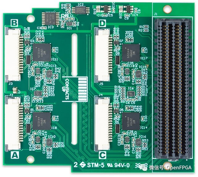
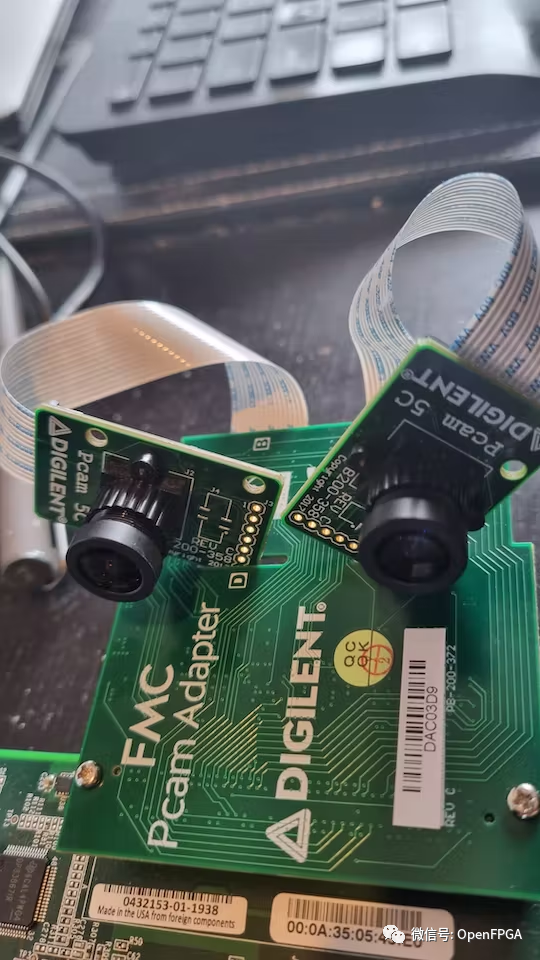
本项目主要使用 Digilent PCAM 扩展板。PCAM 扩展板为最多四个 PCAMS 提供接口。所以只需要有FMC接口的开发板都可以完成本项目移植。
Vivado
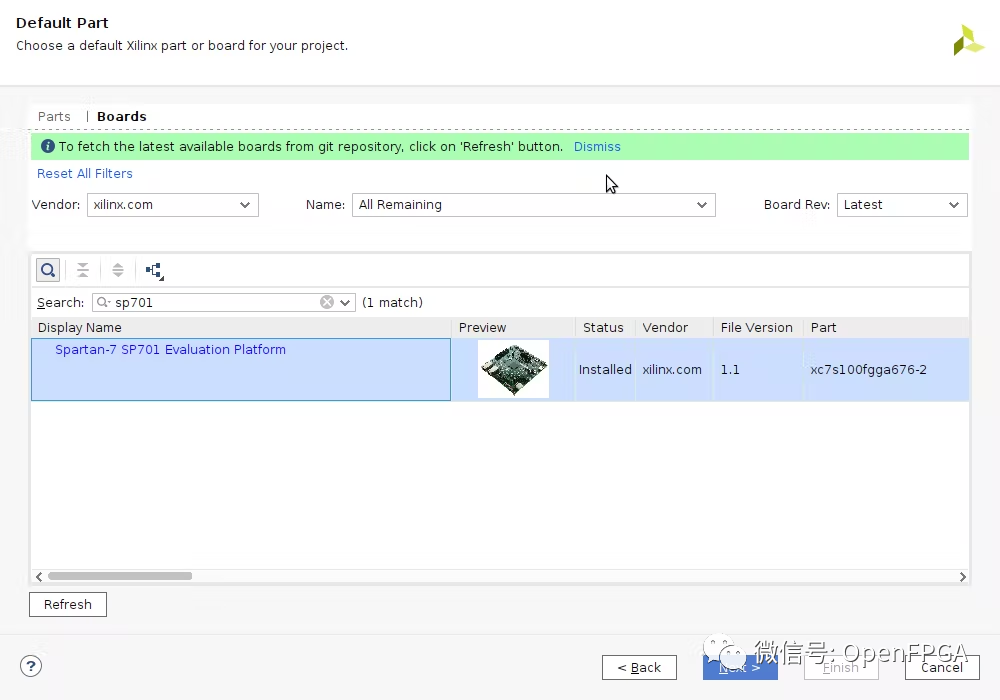
为了让系统快速启动和运行,我们将从赛灵思的一个示例项目开始设计。要打开参考项目,我们需要首先创建一个针对自己开发板上 FPGA 的项目。
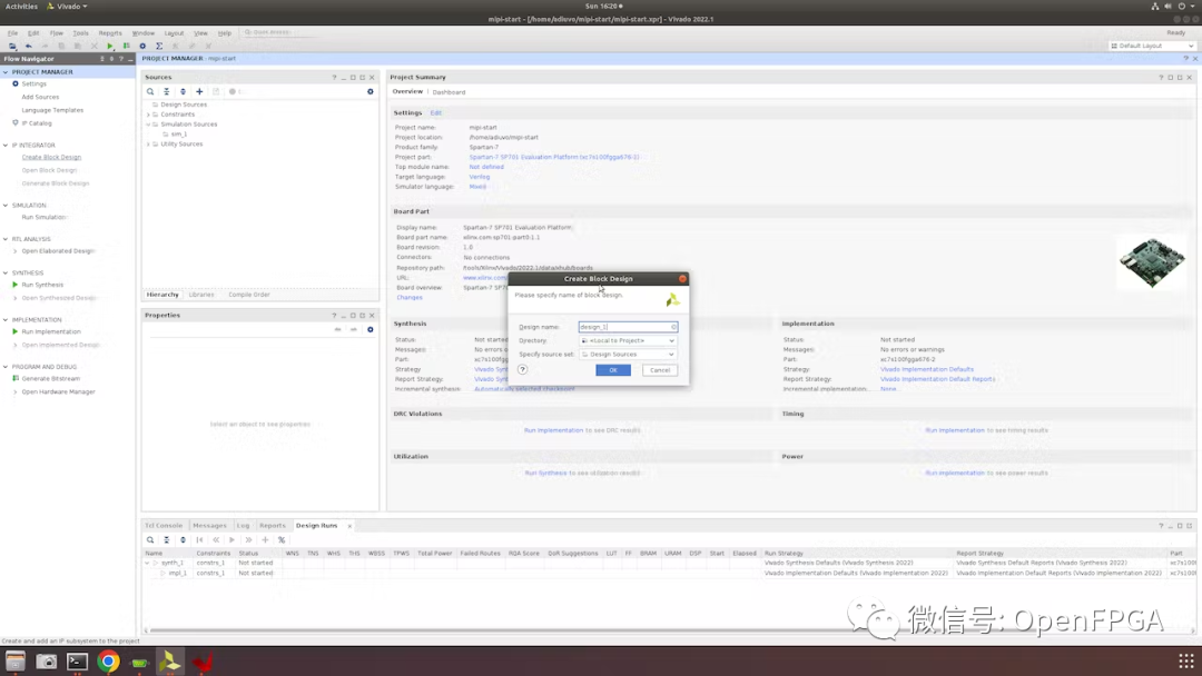
打开项目后,创建一个新的BD。
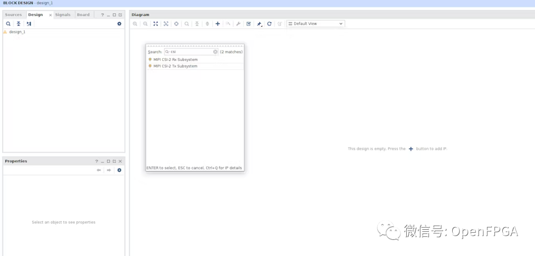
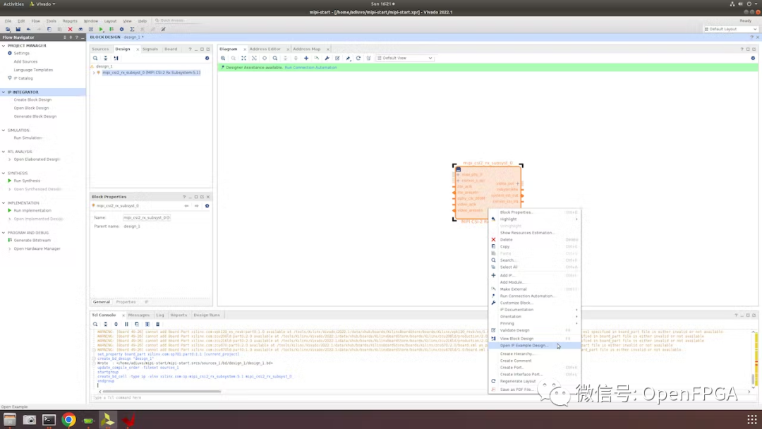
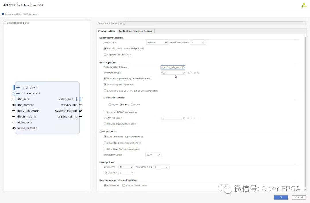
打开BD后,在BD中添加一个 MIPI CSI2 IP。
要打开参考设计,右键单击 CSI2 IP并选择打开 IP 示例设计。
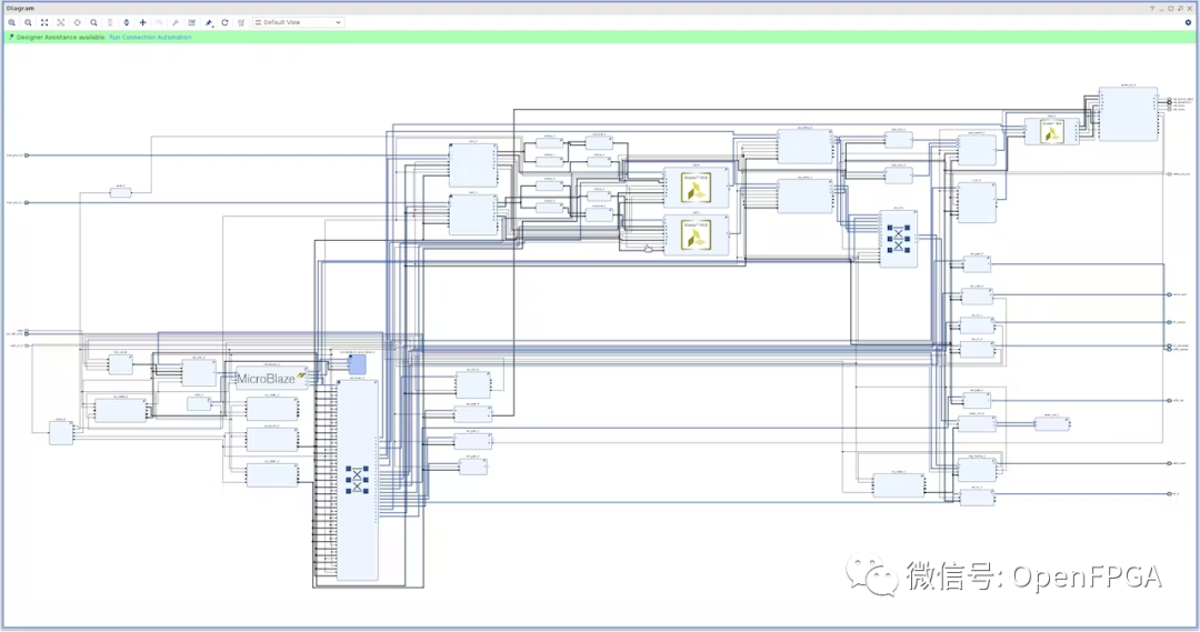
我们将使用这个参考项目。首先要做的是移除 DSI 输出路径。这将为我们的图像处理平台释放 FPGA 中的逻辑资源。
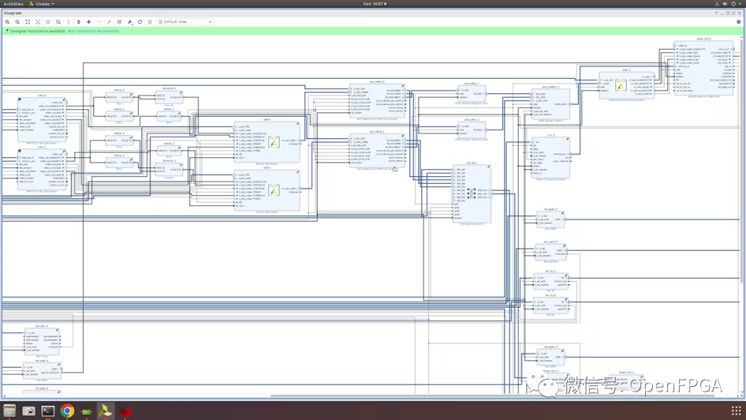
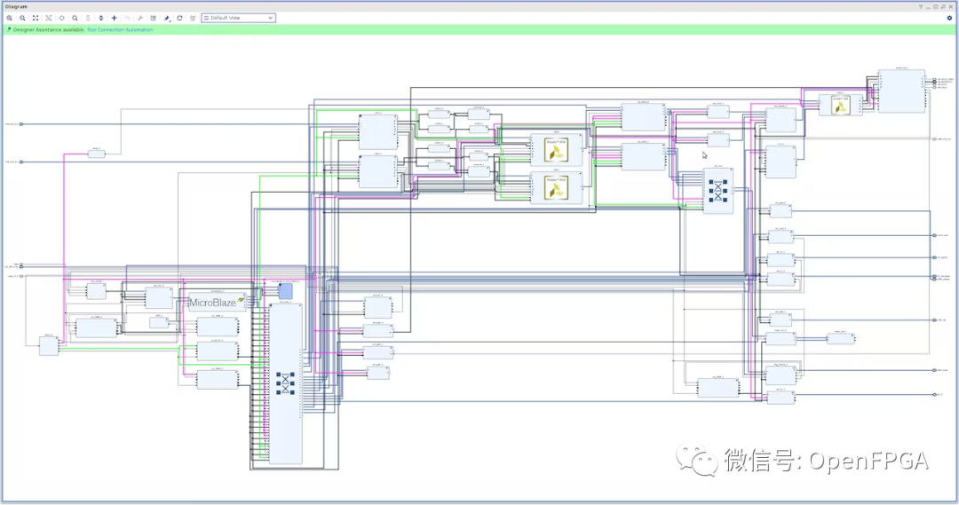
下一步是添加以下元素以创建第二条图像处理通道。
完成的设计应如下所示:
除了 CSI2 IP 中的设置外,第二个图像处理通道与第一个相同。
原始 CSI2 IP 设置
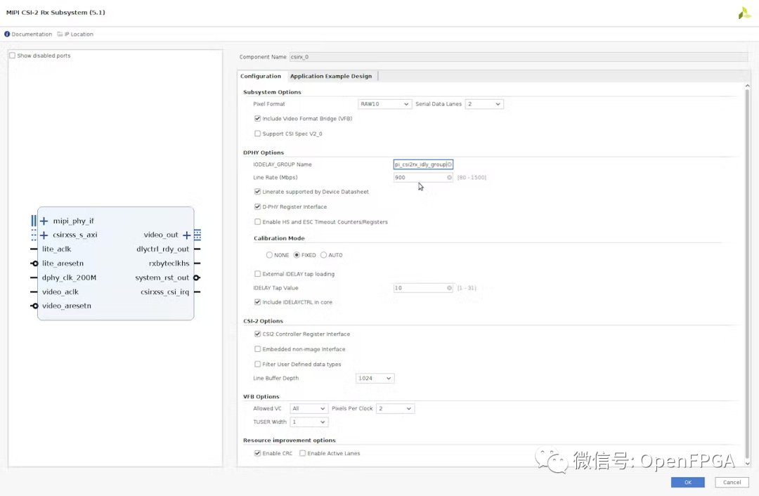
添加的 CSI2 IP 中的设置
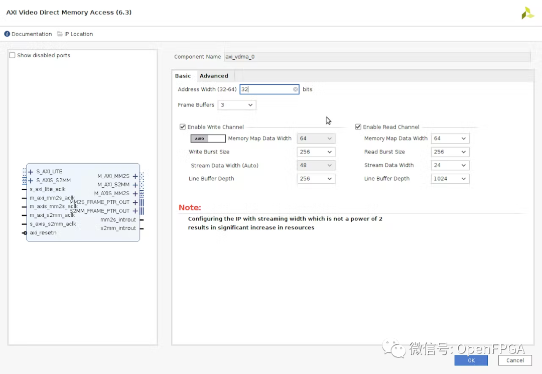
VDMA 内存设置
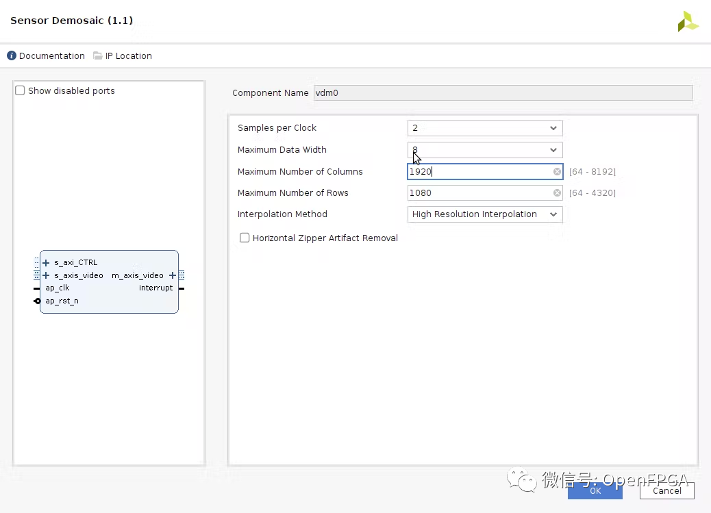
Sensor Demosaic设置
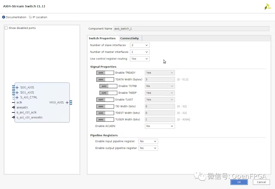
AXI4 Stream Switch
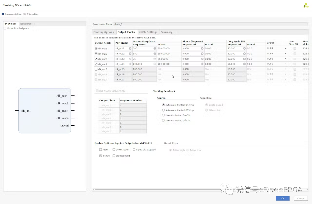
时钟有不同的上行和下行时钟
完成BD设计接下来就是针对硬件进行管脚约束。
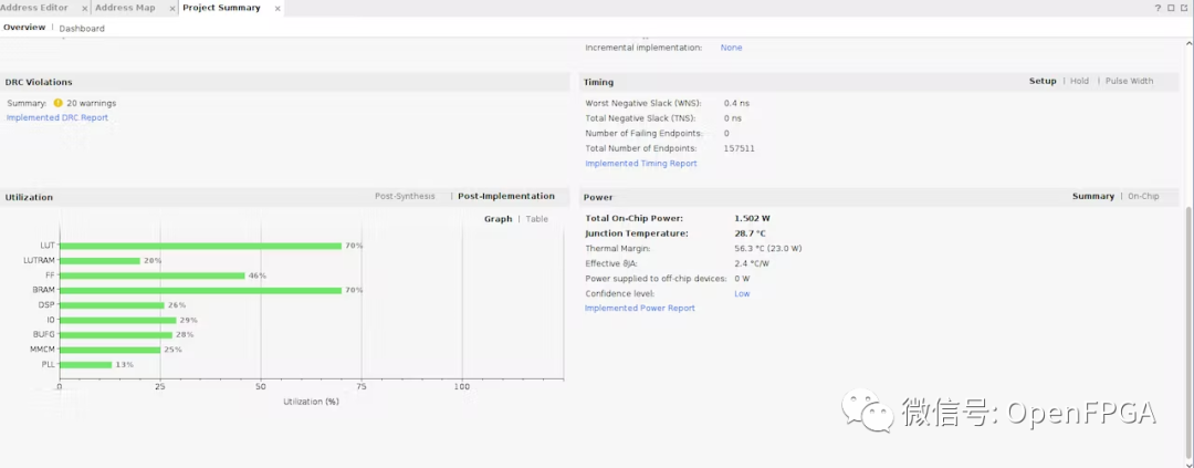
一旦完成,我们就可以生成和构建项目并导出 XSA 用于软件开发。
该设备的利用率如下:
软件开发
导出 XSA 后,我们可以创建一个新的 Vitis 项目,其中包含 hello world 应用程序。
从 hello world 应用程序 BSP 设置中,我们可以导入 MIPI CSI2 示例项目。
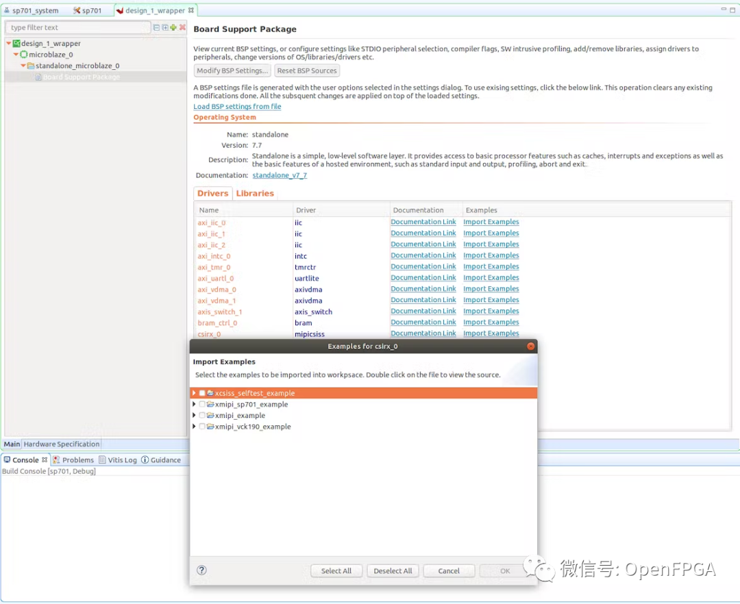
我们需要对这个项目进行一些更改。
首先是通过 IIC 与传感器通信并设置传感器。板上的 CSI2 Sensor与FPGA 的 I2C 并没有直接连接。通过一个I2C BUFFER,与四个sensor连接,因为sensor的地址是一样的。
这可以在 fucntion_prototpye.c 中提供的传感器配置函数中进行更改。
所以我们在配置运行之前需要选择多路复用器。
externintSensorPreConfig(intpcam5c_mode){


u32Index,MaxIndex,MaxIndex1,MaxIndex2;
intStatus;
SensorIicAddr=SENSOR_ADDRESS;

u8SP701mux_addr=0x75;
u8SP701mux_ch=0x40;

u8PCAM_FMC_addr=0x70;
u8PCAM_FMC_ch=0x01;


Status=XIic_SetAddress(&IicAdapter,XII_ADDR_TO_SEND_TYPE,SP701mux_addr);
if(Status!=XST_SUCCESS){
returnXST_FAILURE;
}

WriteBuffer[0]=SP701mux_ch;
Status=AdapterWriteData(1);
if(Status!=XST_SUCCESS){
printf("sp701muxfailed

");
returnXST_FAILURE;
}

Status=XIic_SetAddress(&IicAdapter,XII_ADDR_TO_SEND_TYPE,PCAM_FMC_addr);
if(Status!=XST_SUCCESS){
returnXST_FAILURE;
}

WriteBuffer[0]=PCAM_FMC_ch;
Status=AdapterWriteData(1);
if(Status!=XST_SUCCESS){
printf("pcammuxfailed

");
returnXST_FAILURE;
}


Status=XIic_SetAddress(&IicAdapter,XII_ADDR_TO_SEND_TYPE,SensorIicAddr);
if(Status!=XST_SUCCESS){
returnXST_FAILURE;
}


WritetoReg(0x31,0x03,0x11);
WritetoReg(0x30,0x08,0x82);

Sensor_Delay();


MaxIndex=length_sensor_pre;
for(Index=0;Index< (MaxIndex - 0); Index++)
  {
    WriteBuffer[0] = sensor_pre[Index].Address >>8;
WriteBuffer[1]=sensor_pre[Index].Address;
WriteBuffer[2]=sensor_pre[Index].Data;

Sensor_Delay();

Status=AdapterWriteData(3);
if(Status!=XST_SUCCESS){
returnXST_FAILURE;
}
}


WritetoReg(0x30,0x08,0x42);


MaxIndex1=length_pcam5c_mode1;

for(Index=0;Index< (MaxIndex1 - 0); Index++)
  {
    WriteBuffer[0] = pcam5c_mode1[Index].Address >>8;
WriteBuffer[1]=pcam5c_mode1[Index].Address;
WriteBuffer[2]=pcam5c_mode1[Index].Data;

Sensor_Delay();

Status=AdapterWriteData(3);
if(Status!=XST_SUCCESS){
returnXST_FAILURE;
}
}


WritetoReg(0x30,0x08,0x02);
Sensor_Delay();
WritetoReg(0x30,0x08,0x42);


MaxIndex2=length_sensor_list;

for(Index=0;Index< (MaxIndex2 - 0); Index++)
  {
    WriteBuffer[0] = sensor_list[Index].Address >>8;
WriteBuffer[1]=sensor_list[Index].Address;
WriteBuffer[2]=sensor_list[Index].Data;

Sensor_Delay();

Status=AdapterWriteData(3);
if(Status!=XST_SUCCESS){
returnXST_FAILURE;
}
}


if(Status!=XST_SUCCESS){
xil_printf("Error:inWritingentrystatus=%x
",Status);
returnXST_FAILURE;
}

returnXST_SUCCESS;

}
由于我们添加了第二个 Demosaic,我们还需要更新其配置。
intdemosaic()
{
demosaic_Config=XV_demosaic_LookupConfig(DEMOSAIC_DEVICE_ID);
XV_demosaic_CfgInitialize(&InstancePtr,demosaic_Config,
demosaic_Config->BaseAddress);
XV_demosaic_Set_HwReg_width(&InstancePtr,1920);
XV_demosaic_Set_HwReg_height(&InstancePtr,1080);
XV_demosaic_Set_HwReg_bayer_phase(&InstancePtr,0x3);
XV_demosaic_EnableAutoRestart(&InstancePtr);
XV_demosaic_Start(&InstancePtr);

demosaic_Config1=XV_demosaic_LookupConfig(DEMOSAIC_DEVICE1_ID);
XV_demosaic_CfgInitialize(&InstancePtr1,demosaic_Config1,
demosaic_Config1->BaseAddress);
XV_demosaic_Set_HwReg_width(&InstancePtr1,1920);
XV_demosaic_Set_HwReg_height(&InstancePtr1,1080);
XV_demosaic_Set_HwReg_bayer_phase(&InstancePtr1,0x3);
XV_demosaic_EnableAutoRestart(&InstancePtr1);
XV_demosaic_Start(&InstancePtr1);
returnXST_SUCCESS;

}
最后阶段是设置第二个 DMA,这里必须注意 DDR3地址管理以确保帧不会相互重叠。
intvdma_hdmi(){

InitVprocSs_CSC(1);

ResetVDMA();

RunVDMA(&AxiVdma,XPAR_AXI_VDMA_0_DEVICE_ID,HORIZONTAL_RESOLUTION,
VERTICAL_RESOLUTION,srcBuffer,FRAME_COUNTER,0);

RunVDMA(&AxiVdma1,XPAR_AXI_VDMA_1_DEVICE_ID,HORIZONTAL_RESOLUTION,
VERTICAL_RESOLUTION,srcBuffer1,FRAME_COUNTER,0);

returnXST_SUCCESS;

}
我们还需要注释掉 DSI 和TPG等函数使用的任何代码。
主代码也需要更新,以便在串口命令下控制 AXI Switch。
/******************************************************************************
*Copyright(C)2018-2022Xilinx,Inc.Allrightsreserved.
*SPDX-License-Identifier:MIT
*******************************************************************************/
/*****************************************************************************/
/**
*
*@filexmipi_sp701_example.c
*
*
*MODIFICATIONHISTORY:
*
*VerWhoDateChanges
*---------------------------------------------------------------------
*X.XXXXYY/MM/DD
*1.00RHe19/09/20Initialrelease.
*
*
******************************************************************************/
/*****************************IncludeFiles*********************************/
#include"xparameters.h"
#include"xiic.h"
#include"xil_exception.h"
#include"function_prototype.h"
#include"pcam_5C_cfgs.h"
#include"xstatus.h"
#include"sleep.h"
#include"xiic_l.h"
#include"xil_io.h"
#include"xil_types.h"
//#include"xv_tpg.h"
#include"xil_cache.h"
#include"stdio.h"
#include"xaxis_switch.h"
/**************************ConstantDefinitions*****************************/
#definePAGE_SIZE16
#defineXAXIS_SWITCH_DEVICE_IDXPAR_AXIS_SWITCH_0_DEVICE_ID
#defineIIC_BASE_ADDRESSXPAR_IIC_2_BASEADDR
#defineEEPROM_TEST_START_ADDRESS0x80
#defineIIC_SWITCH_ADDRESS0x74
#defineIIC_ADV7511_ADDRESS0x39
//XV_tpg_Config*tpg1_Config;XV_tpg_Config*tpg1_Config;
//XV_tpgtpg1;
//XV_tpgtpg1;
typedefu8AddressType;
typedefstruct{
u8addr;
u8data;
u8init;
}HDMI_REG;
#defineNUMBER_OF_HDMI_REGS16
HDMI_REGhdmi_iic[NUMBER_OF_HDMI_REGS]={
{0x41,0x00,0x10},
{0x98,0x00,0x03},
{0x9A,0x00,0xE0},
{0x9C,0x00,0x30},
{0x9D,0x00,0x61},
{0xA2,0x00,0xA4},
{0xA3,0x00,0xA4},
{0xE0,0x00,0xD0},
{0xF9,0x00,0x00},
{0x18,0x00,0xE7},
{0x55,0x00,0x00},
{0x56,0x00,0x28},
{0xD6,0x00,0xC0},
{0xAF,0x00,0x4},
{0xF9,0x00,0x00}
};
u8EepromIicAddr;/*VariableforstoringEepromIICaddress*/
intIicLowLevelDynEeprom();
u8EepromReadByte(AddressTypeAddress,u8*BufferPtr,u8ByteCount);
u8EepromWriteByte(AddressTypeAddress,u8*BufferPtr,u8ByteCount);
/****************i************TypeDefinitions*******************************/
typedefu8AddressType;
/**************************VariableDefinitions*****************************/
externXIicIicFmc,IicAdapter;/*IICdevice.*/
//HDMIIIC
intIicLowLevelDynEeprom()
{
u8BytesRead;
u32StatusReg;
u8Index;
intStatus;
u32i;
EepromIicAddr=IIC_SWITCH_ADDRESS;
Status=XIic_DynInit(IIC_BASE_ADDRESS);
if(Status!=XST_SUCCESS){
returnXST_FAILURE;
}
xil_printf("
AfterXIic_DynInit
");
while(((StatusReg=XIic_ReadReg(IIC_BASE_ADDRESS,
XIIC_SR_REG_OFFSET))&
(XIIC_SR_RX_FIFO_EMPTY_MASK|
XIIC_SR_TX_FIFO_EMPTY_MASK|
XIIC_SR_BUS_BUSY_MASK))!=
(XIIC_SR_RX_FIFO_EMPTY_MASK|
XIIC_SR_TX_FIFO_EMPTY_MASK)){
}
EepromIicAddr=IIC_ADV7511_ADDRESS;
for(Index=0;Index< NUMBER_OF_HDMI_REGS; Index++)
{
EepromWriteByte(hdmi_iic[Index].addr, &hdmi_iic[Index].init, 1);
}
for(Index=0;Index< NUMBER_OF_HDMI_REGS; Index++)
{
BytesRead = EepromReadByte(hdmi_iic[Index].addr, &hdmi_iic[Index].data, 1);
for(i=0;i<1000;i++) {}; // IIC delay
if(BytesRead!=1){
returnXST_FAILURE;
}
}
returnXST_SUCCESS;
}
/*****************************************************************************/
/**
*ThisfunctionwritesabufferofbytestotheIICserialEEPROM.
*
*@paramBufferPtrcontainstheaddressofthedatatowrite.
*@paramByteCountcontainsthenumberofbytesinthebuffertobe
*written.Notethatthisshouldnotexceedthepagesizeofthe
*EEPROMasnotedbytheconstantPAGE_SIZE.
*
*@returnThenumberofbyteswritten,avaluelessthanthatwhichwas
*specifiedasaninputindicatesanerror.
*
*@noteone.
*
******************************************************************************/
u8EepromWriteByte(AddressTypeAddress,u8*BufferPtr,u8ByteCount)
{
u8SentByteCount;
u8WriteBuffer[sizeof(Address)+PAGE_SIZE];
u8Index;
/*
*Atemporarywritebuffermustbeusedwhichcontainsboththeaddress
*andthedatatobewritten,puttheaddressinfirstbaseduponthe
*sizeoftheaddressfortheEEPROM
*/
if(sizeof(AddressType)==2){
WriteBuffer[0]=(u8)(Address>>8);
WriteBuffer[1]=(u8)(Address);
}elseif(sizeof(AddressType)==1){
WriteBuffer[0]=(u8)(Address);
EepromIicAddr|=(EEPROM_TEST_START_ADDRESS>>8)&0x7;
}
/*
*Putthedatainthewritebufferfollowingtheaddress.
*/
for(Index=0;Index< ByteCount; Index++) {
WriteBuffer[sizeof(Address) + Index] = BufferPtr[Index];
}
/*
* Write a page of data at the specified address to the EEPROM.
*/
SentByteCount = XIic_DynSend(IIC_BASE_ADDRESS, EepromIicAddr,
WriteBuffer, sizeof(Address) + ByteCount,
XIIC_STOP);
/*
* Return the number of bytes written to the EEPROM.
*/
returnSentByteCount-sizeof(Address);
}
/******************************************************************************
*
*ThisfunctionreadsanumberofbytesfromtheIICserialEEPROMintoa
*specifiedbuffer.
*
*@paramBufferPtrcontainstheaddressofthedatabuffertobefilled.
*@paramByteCountcontainsthenumberofbytesinthebuffertoberead.
*Thisvalueisconstrainedbythepagesizeofthedevicesuch
*thatupto64Kmaybereadinonecall.
*
*@returnThenumberofbytesread.Avaluelessthanthespecifiedinput
*valueindicatesanerror.
*
*@noteNone.
*
******************************************************************************/
u8EepromReadByte(AddressTypeAddress,u8*BufferPtr,u8ByteCount)
{
u8ReceivedByteCount;
u8SentByteCount;
u16StatusReg;
/*
*PositiontheReadpointertospecificlocationintheEEPROM.
*/
do{
StatusReg=XIic_ReadReg(IIC_BASE_ADDRESS,XIIC_SR_REG_OFFSET);
if(!(StatusReg&XIIC_SR_BUS_BUSY_MASK)){
SentByteCount=XIic_DynSend(IIC_BASE_ADDRESS,EepromIicAddr,
(u8*)&Address,sizeof(Address),XIIC_REPEATED_START);
}
}while(SentByteCount!=sizeof(Address));
/*
*Receivethedata.
*/
ReceivedByteCount=XIic_DynRecv(IIC_BASE_ADDRESS,EepromIicAddr,
BufferPtr,ByteCount);
/*
*ReturnthenumberofbytesreceivedfromtheEEPROM.
*/
returnReceivedByteCount;
}
/*****************************************************************************/
/**
*
*MainfunctiontoinitializeinteropsystemandreaddatafromAR0330sensor
*@paramNone.
*
*@return
*-XST_SUCCESSifMIPIInteropwassuccessful.
*-XST_FAILUREifMIPIInteropfailed.
*
*@noteNone.
*
******************************************************************************/
intmain(){
intStatus;
intpcam5c_mode=1;
intusr_entry,prev_sel;
intdefault_input;
intdsi_hdmi_select=0;
Xil_ICacheDisable();
Xil_DCacheDisable();
XAxis_SwitchAxisSwitch;
XAxis_Switch_Config*ASWConfig;
ASWConfig=XAxisScr_LookupConfig(XAXIS_SWITCH_DEVICE_ID);
XAxisScr_CfgInitialize(&AxisSwitch,ASWConfig,ASWConfig->BaseAddress);
XAxisScr_RegUpdateDisable(&AxisSwitch);
XAxisScr_MiPortDisableAll(&AxisSwitch);
XAxisScr_MiPortEnable(&AxisSwitch,0,0);
XAxisScr_RegUpdateEnable(&AxisSwitch);
xil_printf("
******************************************************
");
xil_printf("
**SP701ExampleDesign**");
Status=IicLowLevelDynEeprom();
if(Status!=XST_SUCCESS){
xil_printf("ADV7511IICprogrammingFAILED
");
returnXST_FAILURE;
}
xil_printf("ADV7511IICprogrammingPASSED
");
//InitializeFMC,AdapterandSensorIIC
Status=InitIIC();
if(Status!=XST_SUCCESS){
xil_printf("
IICinitializationFailed
");
returnXST_FAILURE;
}
xil_printf("IICInitializtionDone
");
//InitializeFMCInterruptSystem
Status=SetupFmcInterruptSystem(&IicFmc);
if(Status!=XST_SUCCESS){
xil_printf("
InterruptSystemInitializationFailed
");
returnXST_FAILURE;
}
xil_printf("FMCInterruptSystemInitializationDone
");
//SetupIICInterruptHandlers
SetupIICIntrHandlers();
xil_printf("IICInterruptHandlersSetupDone
");
Status=SetFmcIICAddress();
if(Status!=XST_SUCCESS){
xil_printf("
FMCIICAddressSetupFailed
");
returnXST_FAILURE;
}
xil_printf("FmcIICAddressSet
");
//InitializeAdapterInterruptSystem
Status=SetupAdapterInterruptSystem(&IicAdapter);
if(Status!=XST_SUCCESS){
xil_printf("
InterruptSystemInitializationFailed
");
returnXST_FAILURE;
}
xil_printf("AdapterInterruptSystemInitializationDone
");
//SetAddressofAdapterIIC
Status=SetAdapterIICAddress();
if(Status!=XST_SUCCESS){
xil_printf("
AdapterIICAddressSetupFailed
");
returnXST_FAILURE;
}
xil_printf("AdapterIICAddressSet
");
Status=InitializeCsiRxSs();
if(Status!=XST_SUCCESS){
xil_printf("CSIRxSsInitfailedstatus=%x.
",Status);
returnXST_FAILURE;
}
dsi_hdmi_select=0;
//usingdefault_inputvartocomparesameoptionselection
default_input=1;
//SetupDSI();
resetIp();
EnableCSI();
GPIOSelect(dsi_hdmi_select);
Status=demosaic();
if(Status!=XST_SUCCESS){
xil_printf("
DemosaicFailed
");
returnXST_FAILURE;
}
CamReset();
//PreconifgureSensor
Status=SensorPreConfig(pcam5c_mode);
if(Status!=XST_SUCCESS){
xil_printf("
SensorPreConfigurationFailed
");
returnXST_FAILURE;
}
xil_printf("
Sensor1isPreConfigured
");
WritetoReg(0x30,0x08,0x02);
//PreconifgureSensor
Status=SensorPreConfig1(pcam5c_mode);
if(Status!=XST_SUCCESS){
xil_printf("
SensorPreConfigurationFailed
");
returnXST_FAILURE;
}
xil_printf("
Sensor2isPreConfigured
");
WritetoReg(0x30,0x08,0x02);
Status=vdma_hdmi();
if(Status!=XST_SUCCESS){
xil_printf("
Vdma_hdmiFailed
");
returnXST_FAILURE;
}
Status=vtpg_hdmi();
if(Status!=XST_SUCCESS){
xil_printf("
VtpgFailed
");
returnXST_FAILURE;
}
Sensor_Delay();
xil_printf("
PipelineConfigurationCompleted
");
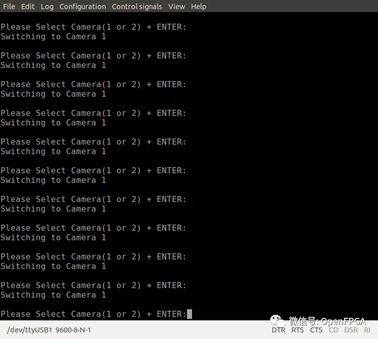
while(1){
xil_printf("
PleaseSelectCamera(1or2)+ENTER:");
usr_entry=getchar();
charb;
scanf("%c",&b);//ThiswilltakeENTERkey
switch(usr_entry){
case'1':
xil_printf("
SwitchingtoCamera1
");
XAxisScr_RegUpdateDisable(&AxisSwitch);
XAxisScr_MiPortDisableAll(&AxisSwitch);
XAxisScr_MiPortEnable(&AxisSwitch,0,0);
XAxisScr_RegUpdateEnable(&AxisSwitch);
break;
case'2':
xil_printf("
SwitchingtoCamera1
");
XAxisScr_RegUpdateDisable(&AxisSwitch);
XAxisScr_MiPortDisableAll(&AxisSwitch);
XAxisScr_MiPortEnable(&AxisSwitch,0,1);
XAxisScr_RegUpdateEnable(&AxisSwitch);
break;
default:
xil_printf("
Selectionisunavailable.Pleasetryagain
");
break;
}
}
returnXST_SUCCESS;
}
测试
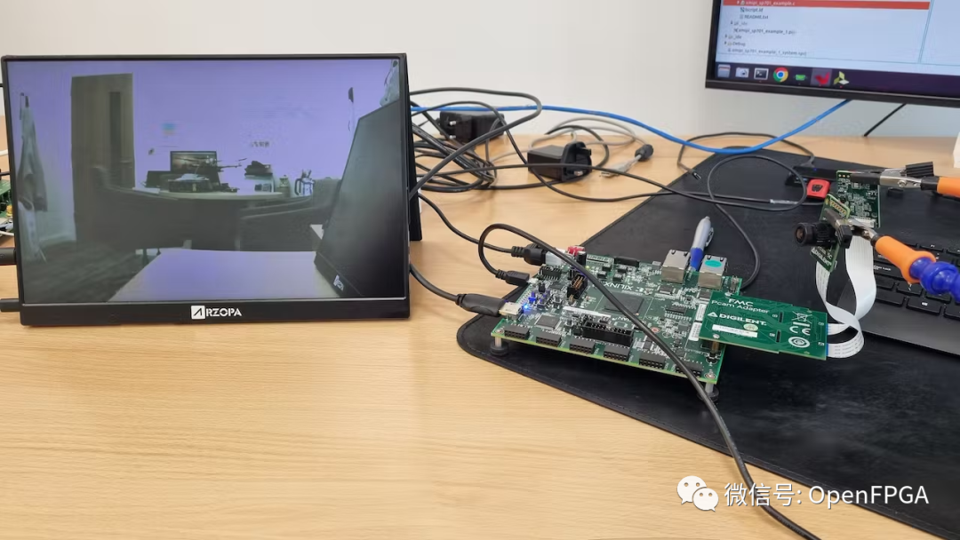
我们可以在连接到 HDMI 输出时运行应用程序并在显示器上看到图像。
使用应用程序选择图像。

参考
https://www.hackster.io/
总结
该项目展示了一个MIPI摄像头接入FPGA的简单、快捷的方式,同时可以学习一下软件的导入工程的方式,简单的基于MicroBlaze系统要学会自己写控制代码,也许这就是新一代“FPGA打工人”需要掌握的一项新技术吧~(doge~不是)
示例工程
https://github.com/ATaylorCEngFIET/Hackster/tree/master
https://github.com/ATaylorCEngFIET/SP701_Imaging_Vivado
审核编辑 :李倩
-
FPGA
+关注
关注
1631文章
21806浏览量
606681 -
摄像头
+关注
关注
60文章
4872浏览量
96486 -
图像系统
+关注
关注
0文章
10浏览量
7082
原文标题:示例工程
文章出处:【微信号:Open_FPGA,微信公众号:OpenFPGA】欢迎添加关注!文章转载请注明出处。
发布评论请先 登录
相关推荐
米尔瑞芯微RK3576实测轻松搞定三屏八摄像头
积水自动监控摄像头
摄像头及红外成像的基本工作原理

飞凌嵌入式-ELFBOARD-OV5640摄像头简介
飞凌嵌入式-ELFBOARD-OV5640摄像头简介第一期
《DNK210使用指南 -CanMV版 V1.0》第二十七章 摄像头图像调整实验
《DNK210使用指南 -CanMV版 V1.0》第二十六章 摄像头图像捕获实验

基于RK3588J的6路MIPI CSI视频采集案例分享,多路视频系统必看!
如何通过RK3576配置MIPI-CSI摄像头的不同输出格式
基于FPGA的摄像头心率检测装置设计
智能摄像头抄表器是什么?
摄像头各标定参数的作用


 工商网监
工商网监
评论