2.1 原理图分析
查看EK-RA6M4的原理图,如下图所示,该开发板上有3个Led指示灯。

根据原理图可知,这三个Led的控制逻辑为:
| Led灯 | LED3 | LED2 | LED1 |
|---|---|---|---|
| 颜色 | 红色 | 绿色 | 蓝色 |
| 引脚 | P400 | P404 | P415 |
| 电平 | 高电平亮、低电平灭 | 高电平亮、低电平灭 | 高电平亮、低电平灭 |
2.2 创建工程
在开始菜单的FSP v4.1.0里点击运行e2studio。然后点击 File -> Switch Workspace -> Other... ,然后选择刚才创建的工作路径并点击 Launch启动。

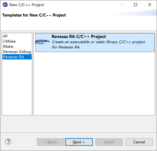
接下来点击 File -> C/C++ Project 创建 Renesas RA C/C++ Project 。接下来设置我们的项目名为 MyBoard 。
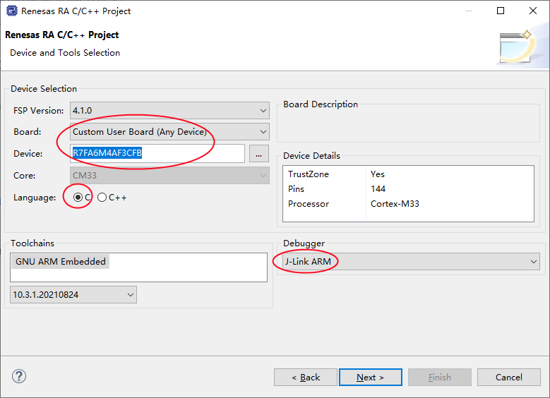
在接下来的配置中,我们定制开发我们的开发板,Board选择“Custom User Board (Any Device) ”,Device选择"R7FA6M4AF3CFB",以及烧录调试器的类型。下一步我们就选择 Flat (Non-TrustZone) Project 。
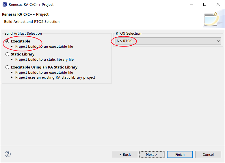
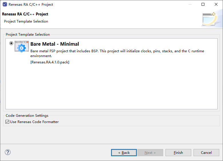
项目模板选择 Bare Metal -Minimal
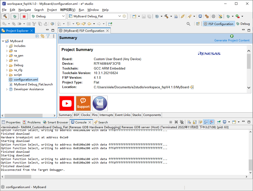
接下来,创建好的项目如下图所示。
2.3 Pins引脚配置
接下来我们打开项目中的FSP配置文件,配置三个Led灯的引脚为GPIO模式,并分别配置它们的别名为LedRed(P400)、LedGreen(P404)、LedBlue(P415)。
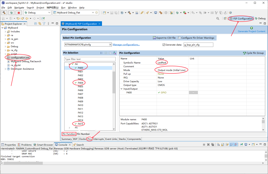
- 通过 Symbolic Name 字段可以修改该GPIO的名称为 LedRed,它将在IDE自动生成的文件 ra_cfg/fsp_cfg/bsp/bsp_pin_cfg.h 中定义;
- 通过 Mode 字段可以修改GPIO口的工作模式,它们将在IDE自动生成的文件 ra_gen/pin_data.c 中定义;
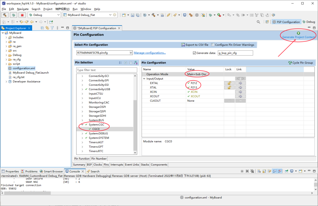
然后再配置使能外部晶振,并重新生成代码。
2.4 Stack配置
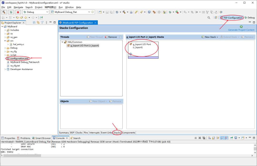
e2studio生成的项目,默认添加的GPIO的stack,这里我们不需要进行任何的修改。
2.5 源码修改
接下来,我们使用添加 src/bsp_led.h 头文件,在里面添加Led的相关定义及操作函数声明如下:
#ifndef BSP_LED_H_
#define BSP_LED_H_

/** Information on how many LEDs and what pins they are on. */
typedef struct st_bsp_leds
{
    uint16_t         led_count;        ///< The number of LEDs on this board
    uint16_t const * p_leds;           ///< Pointer to an array of IOPORT pins for controlling LEDs
} bsp_leds_t;

/** Available user-controllable LEDs on this board. These enums can be can be used to index into the array of LED pins
 * found in the bsp_leds_t structure. */
typedef enum e_bsp_led
{
    BSP_LEDBLUE,                      ///< LED1
    BSP_LEDGREEN,                     ///< LED2
    BSP_LEDRED,                       ///< LED3
} bsp_led_t;

/** Available user-controllable LEDs on this board. These enums can be used to turn on/off LED. */
typedef enum e_bsp_led_status
{
    BSP_LEDOFF,                      ///< Turn off LED
    BSP_LEDON,                       ///< Turn on  LED
} bsp_led_status_t;

extern const bsp_leds_t g_bsp_leds;

extern void turn_led(bsp_led_t which, bsp_led_status_t status);

#endif /* BSP_LED_H_ */
然后再添加 src/bsp_led.c 源文件如下:
#include "bsp_api.h"
#include "bsp_led.h"
#include "bsp_pin_cfg.h"

/** Array of LED IOPORT pins. */
static const uint16_t g_bsp_prv_leds[] =
{
    (uint16_t) LedBlue,
    (uint16_t) LedGreen,
    (uint16_t) LedRed,
};


/** Structure with LED information for this board. */
const bsp_leds_t g_bsp_leds =
{
    .led_count = (uint16_t) ((sizeof(g_bsp_prv_leds) / sizeof(g_bsp_prv_leds[0]))),
    .p_leds    = &g_bsp_prv_leds[0]
};

/** Function to turn Led on or off for this board. */
void turn_led(bsp_led_t which, bsp_led_status_t status)
{
    if(which >= g_bsp_leds.led_count )
    {
        return ;
    }

    if( BSP_LEDOFF == status )
    {
        R_BSP_PinWrite(g_bsp_leds.p_leds[which], BSP_IO_LEVEL_LOW);
    }
    else
    {
        R_BSP_PinWrite(g_bsp_leds.p_leds[which], BSP_IO_LEVEL_HIGH);
    }
}
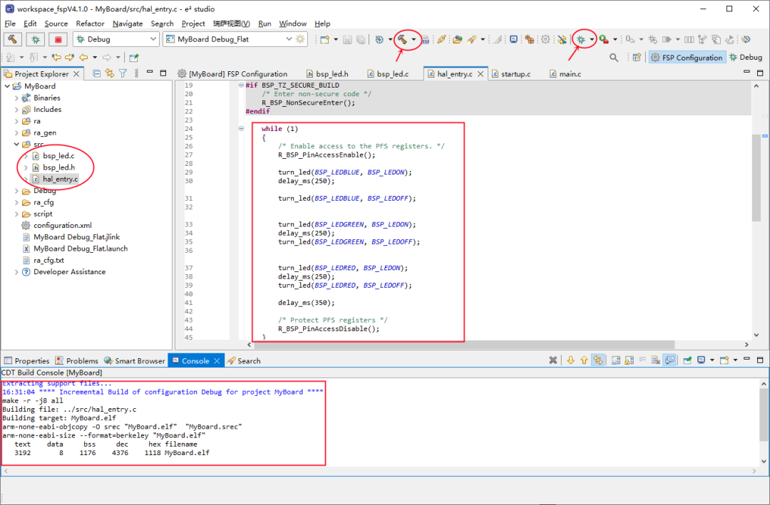
接下来,我们可以修改 src/hal_entry.c 源文件,在里面添加毫秒级延时宏函数 delay_ms() 以及 Led 跑马灯的控制代码。
#include "bsp_led.h"

#define delay_ms(ms)  R_BSP_SoftwareDelay(ms, BSP_DELAY_UNITS_MILLISECONDS)
... ...

void hal_entry(void)
{
    /* TODO: add your own code here */

#if BSP_TZ_SECURE_BUILD
    /* Enter non-secure code */
    R_BSP_NonSecureEnter();
#endif

    R_BSP_PinAccessEnable(); /* Enable access to the PFS registers. */
    while (1)
    {
        turn_led(BSP_LEDBLUE, BSP_LEDON);
        delay_ms(250);
        turn_led(BSP_LEDBLUE, BSP_LEDOFF);

        turn_led(BSP_LEDGREEN, BSP_LEDON);
        delay_ms(250);
        turn_led(BSP_LEDGREEN, BSP_LEDOFF);

        turn_led(BSP_LEDRED, BSP_LEDON);
        delay_ms(250);
        turn_led(BSP_LEDRED, BSP_LEDOFF);

        delay_ms(350);
    }
}
- R_BSP_PinAccessEnable() 函数必须使能,否则不能操作GPIO的寄存器;
2.5 编译运行
代码修改完成后,在开发板上编译运行,会发现三个Led跑马灯运行。
-
led
+关注
关注
242文章
23286浏览量
661058 -
单片机
+关注
关注
6037文章
44561浏览量
635565 -
瑞萨
+关注
关注
35文章
22309浏览量
86348 -
跑马灯
+关注
关注
5文章
117浏览量
34791
发布评论请先 登录
相关推荐


 基于单片机的Led跑马灯实现






评论