01FPGA图像仿真方法概述
VHDL和Verilog代码编写后通常需要编写激励文件进行仿真以验证代码的可行性,通过仿真可以及时排查代码存在的时序问题,有效提高代码实现效率。
图像数据量通常较大,1920×1080@60Hz分辨率的图像通常需要1920×1080个8bit寄存器reg,因此在仿真中通常难以直接编写语句生成相应的代码,因此需要借助相应图像格式文件的读取操作和文件格式转换工具辅助。
Matlab是图像算法设计验证常用工具,因此主要以Matlab为辅助工具,对FPGA图像仿真方法进行介绍,通常采用以下3种方法:
1. .txt格式图像仿真方法:Verilog代码通常支持通过$readmemh、$readmemb、$fopen等语句读取.txt文本文件,因此可以借助Matlab将图像转换为.txt格式图像文本,编写.txt文件读取代码实现FPGA图像仿真;
2. .coe格式图像仿真方法:EDA工具通常提供ROM IP核支持.coe格式文件存储,因此可以借助Matlab将图像转换为.coe格式文件,将.coe文件存入ROM,通过操作ROM读取图像数据实现FPGA图像仿真;
3. 图像存储模块仿真方法:通过编写图像存储.v或.vhdl模块以供顶层文件读取,由于图像数据量较大,可以借助Matlab工具实现存储模块的编写过程。
02.txt格式图像仿真方法
通过读取.txt格式图像文件实现基于Verilog仿真步骤:
1. 利用Matlab转换.jpg或者其他图像为.txt格式数据;
2. 通过Vivado完成图像读取处理并生成.txt格式文件;
3. 利用Matlab转换显示Vivado处理后的.txt格式图像。
2.1 Matlab生成.txt文件
通过Matlab将图像按16进制转换为.txt格式,文件夹中应包含输入图片cascatrix.jpg:
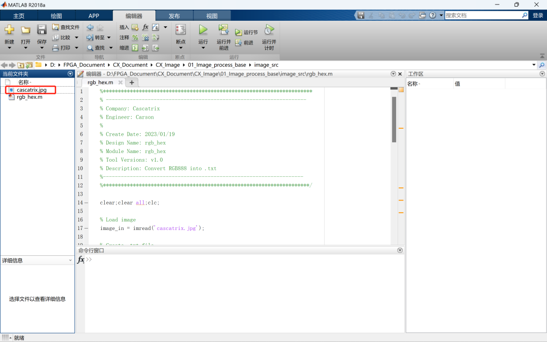

Matlab代码如下:
%**********************************************************************
% -------------------------------------------------------------------
% Company: Cascatrix
% Engineer: Carson
%
% Create Date: 2023/01/19
% Design Name: rgb_hex
% Module Name: rgb_hex
% Tool Versions: v1.0
% Description: Convert RGB888 into .txt
%-------------------------------------------------------------------
%*********************************************************************/
clear;clear all;clc;
% Load image
image_in = imread('cascatrix.jpg');
% Create .txt file
FileName=['image_in','.txt'];
% Get image size
[row,col,n] = size(image_in);
% Write image into image_in.txt
FileImage = fopen(FileName,'w');
for x = 1:row
for y = 1:col
image_r = dec2hex(image_in(x,y,1));
image_g = dec2hex(image_in(x,y,2));
image_b = dec2hex(image_in(x,y,3));
[r_row,r_col]=size(image_r);
[g_row,g_col]=size(image_g);
[b_row,b_col]=size(image_b);
if r_col == 1
image_r =['0',image_r];
elseif r_col == 0
image_r ='00';
end
if g_col == 1
image_g =['0',image_g];
elseif g_col == 0
image_g ='00';
end
if b_col == 1
image_b =['0',image_b];
elseif b_col == 0
image_b ='00';
end
image_hex=[image_r,image_g,image_b,];
fprintf(FileImage,'%s ',image_hex);
end
end
fclose(FileImage);
rgb_hex代码运行后生成.txt格式图像image_in.txt:
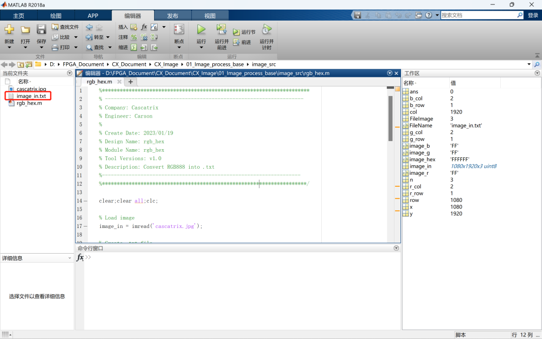

2.2 VIVADO读取与处理
利用Verilog $readmemh语句读取image_in.txt文件:
cx_image.v模块(将.txt文件放置在相应路径):
`timescale 1ns / 1ps
//////////////////////////////////////////////////////////////////////////////////
// Company: Cascatrix
// Engineer: Carson
//
// Create Date: 2023/01/19
// Design Name: Image_Base
// Module Name: cx_image
// Tool Versions: v1.0
// Description: Image read and generate display
//parameters
//////////////////////////////////////////////////////////////////////////////////
`define PIXEL_1920_1080
//`define PIXEL_1680_1050
//`define PIXEL_1280_1024
//`define PIXEL_1280_720
//`define PIXEL_1024_768
//`define PIXEL_800_600
//`define PIXEL_640_480
module cx_image(
inputwireclk,
outputreghsyn,
outputregvsyn,
outputwireen,
outputreg [23:0]data
);
//1920x1080 148.5Mhz
`ifdef PIXEL_1920_1080
parameter H_ACTIVE = 1920;// 行数据有效时间
parameter H_FRONT_PORCH = 88; // 行消隐前肩时间
parameter H_SYNC_TIME = 44; // 行同步信号时间
parameter H_BACK_PORCH = 148; // 行消隐后肩时间
parameter V_ACTIVE = 1080;// 列数据有效时间
parameter V_FRONT_PORCH = 4; // 列消隐前肩时间
parameter V_SYNC_TIME = 5; // 列同步信号时间
parameter V_BACK_PORCH = 36; // 列消隐后肩时间
`endif
//1680x1050 119Mhz
`ifdef PIXEL_1680_1050
parameter H_ACTIVE = 1680;// 行数据有效时间
parameter H_FRONT_PORCH = 48; // 行消隐前肩时间
parameter H_SYNC_TIME = 32; // 行同步信号时间
parameter H_BACK_PORCH = 80; // 行消隐后肩时间
parameter V_ACTIVE = 1050;// 列数据有效时间
parameter V_FRONT_PORCH = 3; // 列消隐前肩时间
parameter V_SYNC_TIME = 6; // 列同步信号时间
parameter V_BACK_PORCH = 21; // 列消隐后肩时间
`endif
//1280x1024 108Mhz
`ifdef PIXEL_1280_1024
parameter H_ACTIVE = 1280;// 行数据有效时间
parameter H_FRONT_PORCH = 48; // 行消隐前肩时间
parameter H_SYNC_TIME = 112; // 行同步信号时间
parameter H_BACK_PORCH = 248; // 行消隐后肩时间
parameter V_ACTIVE = 1024;// 列数据有效时间
parameter V_FRONT_PORCH = 1; // 列消隐前肩时间
parameter V_SYNC_TIME = 3; // 列同步信号时间
parameter V_BACK_PORCH = 38; // 列消隐后肩时间
`endif
//1280X720 74.25MHZ
`ifdef PIXEL_1280_720
parameter H_ACTIVE = 1280;// 行数据有效时间
parameter H_FRONT_PORCH = 110; // 行消隐前肩时间
parameter H_SYNC_TIME = 40; // 行同步信号时间
parameter H_BACK_PORCH = 220; // 行消隐后肩时间
parameter V_ACTIVE = 720; // 列数据有效时间
parameter V_FRONT_PORCH = 5; // 列消隐前肩时间
parameter V_SYNC_TIME = 5; // 列同步信号时间
parameter V_BACK_PORCH = 20; // 列消隐后肩时间
`endif
//1024x768 65Mhz
`ifdef PIXEL_1024_768
parameter H_ACTIVE = 1024;// 行数据有效时间
parameter H_FRONT_PORCH = 24; // 行消隐前肩时间
parameter H_SYNC_TIME = 136; // 行同步信号时间
parameter H_BACK_PORCH = 160; // 行消隐后肩时间
parameter V_ACTIVE = 768; // 列数据有效时间
parameter V_FRONT_PORCH = 3; // 列消隐前肩时间
parameter V_SYNC_TIME = 6; // 列同步信号时间
parameter V_BACK_PORCH = 29; // 列消隐后肩时间
`endif
//800x600 40Mhz
`ifdef PIXEL_800_600
parameter H_ACTIVE = 800;// 行数据有效时间
parameter H_FRONT_PORCH = 40 ;// 行消隐前肩时间
parameter H_SYNC_TIME = 128;// 行同步信号时间
parameter H_BACK_PORCH = 88 ;// 行消隐后肩时间
parameter V_ACTIVE = 600;// 列数据有效时间
parameter V_FRONT_PORCH = 1 ;// 列消隐前肩时间
parameter V_SYNC_TIME = 4 ;// 列同步信号时间
parameter V_BACK_PORCH = 23 ;// 列消隐后肩时间
`endif
//640x480 25.175Mhz
`ifdef PIXEL_640_480
parameter H_ACTIVE = 640; // 行数据有效时间
parameter H_FRONT_PORCH = 16 ; // 行消隐前肩时间
parameter H_SYNC_TIME = 96 ; // 行同步信号时间
parameter H_BACK_PORCH = 48 ; // 行消隐后肩时间
parameter V_ACTIVE = 480; // 列数据有效时间
parameter V_FRONT_PORCH = 10 ; // 列消隐前肩时间
parameter V_SYNC_TIME = 2 ; // 列同步信号时间
parameter V_BACK_PORCH = 33 ; // 列消隐后肩时间
`endif
parameter H_TOTAL_TIME = H_ACTIVE + H_FRONT_PORCH + H_SYNC_TIME + H_BACK_PORCH;
parameter V_TOTAL_TIME = V_ACTIVE + V_FRONT_PORCH + V_SYNC_TIME + V_BACK_PORCH;
reg h_act = 1'b0;
reg v_act = 1'b0;
reg [12:0] h_syn_cnt = 13'b0;
reg [12:0] v_syn_cnt = 13'b0;
reg [23:0] image [0 : H_ACTIVE*V_ACTIVE-1];
reg [31:0] image_cnt = 32'b0;
// 读取.txt文件到image数组中
initial begin
$readmemh("D:/FPGA_Document/CX_Document/CX_Image/ 01_Image_process_base/image_src/image_in.txt", image);
end
// 行扫描计数器
always@(posedge clk)
begin
if(h_syn_cnt == H_TOTAL_TIME-1)
h_syn_cnt <= 13'b0;
else
h_syn_cnt <= h_syn_cnt + 1;
end
// 列扫描计数器
always@(posedge clk)
begin
if(h_syn_cnt == H_TOTAL_TIME-1)
begin
if(v_syn_cnt == V_TOTAL_TIME-1)
v_syn_cnt <= 13'b0;
else
v_syn_cnt <= v_syn_cnt + 1;
end
end
// 行同步控制
always@(posedge clk)
begin
if(h_syn_cnt < H_SYNC_TIME)
hsyn <= 1'b0;
else
hsyn <= 1'b1;
end
// 场同步控制
always@(posedge clk)
begin
if(v_syn_cnt < V_SYNC_TIME)
vsyn <= 1'b0;
else
vsyn <= 1'b1;
end
// 有效数据使能
assign en = h_act & v_act;
// 行有效数据控制
always@(posedge clk)
begin
if(h_syn_cnt == H_SYNC_TIME + H_BACK_PORCH - 1)
h_act = 1'b1;
else if(h_syn_cnt == H_SYNC_TIME + H_BACK_PORCH + H_ACTIVE - 1)
h_act = 1'b0;
end
// 列有效数据控制
always@(posedge clk)
begin
if(v_syn_cnt == V_SYNC_TIME + V_BACK_PORCH - 1 && h_syn_cnt == 0)
v_act = 1'b1;
else if(v_syn_cnt == V_SYNC_TIME + V_BACK_PORCH + V_ACTIVE - 1 && h_syn_cnt == 0)
v_act = 1'b0;
end
// 像素计数器
always@(posedge clk)
begin
if(h_act & v_act)
image_cnt <= image_cnt + 1;
else if(image_cnt == H_ACTIVE*V_ACTIVE - 1)
image_cnt <= 32'b0;
end
// 图像数据
always@(posedge clk)
begin
if(h_act & v_act)
data <= image[image_cnt][23:0];
else
data <= 24'b0;
end
endmodule
利用Verilog $fopen和$fwrite生成.txt图像文件:
cx_tb.v仿真模块(生成图像文件到相应路径):
`timescale 1ns / 1ps
//////////////////////////////////////////////////////////////////////////////////
// Company: Cascatrix
// Engineer: Carson
//
// Create Date: 2023/01/19
// Design Name: Image_Base
// Module Name: cx_tb
// Tool Versions: v1.0
// Description: Image output simulation
//////////////////////////////////////////////////////////////////////////////////
module cx_tb(
);
reg clk;
reg [31:0] pixel_cnt;
wire de;
wire [23:0] data;
integer image_txt;
parameter PIXEL_TOTAL = 1920*1080;
//parameter PIXEL_TOTAL = 1680*1050;
//parameter PIXEL_TOTAL = 1280*1024;
//parameter PIXEL_TOTAL = 1280*720;
//parameter PIXEL_TOTAL = 1024*768;
//parameter PIXEL_TOTAL = 800*600;
//parameter PIXEL_TOTAL = 640*480;
cx_image inst_cx_image
(
.clk (clk ),
.hsyn ( ),
.vsyn ( ),
.en (de ),
.data (data)
);
always #1 clk = ~clk;
initial
begin
clk = 1‘b0;
end
initial
begin
image_txt = $fopen("D:/FPGA_Document/CX_Document/CX _Image/01_Image_process_base/image_src/image_out.txt");
end
always@(posedge clk or negedge rst_n)
begin
if(!rst_n)
begin
pixel_cnt <= 0;
end
else if(de)
begin
pixel_cnt = pixel_cnt + 1;
$fwrite(image_txt,"%h ",data);
end
end
always@(posedge clk)
begin
if(pixel_cnt == PIXEL_TOTAL)
begin
$display("CX: image_out.txt is output completed successfully! %t", $realtime, "ps");
$fclose(image_txt);
$stop;
end
end
endmodule
仿真波形结果:

在指定路径生成处理后的.txt图像文件image_out.txt:
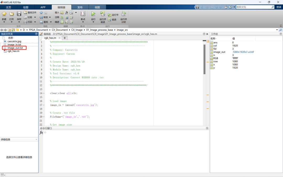
2.3 Matlab显示.txt文件
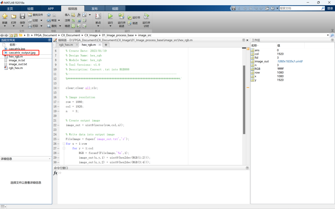
通过Matlab将处理后的.txt图像image_out.txt显示,并转换为jpg或其他格式图像,编写hex_rgb.m文件:
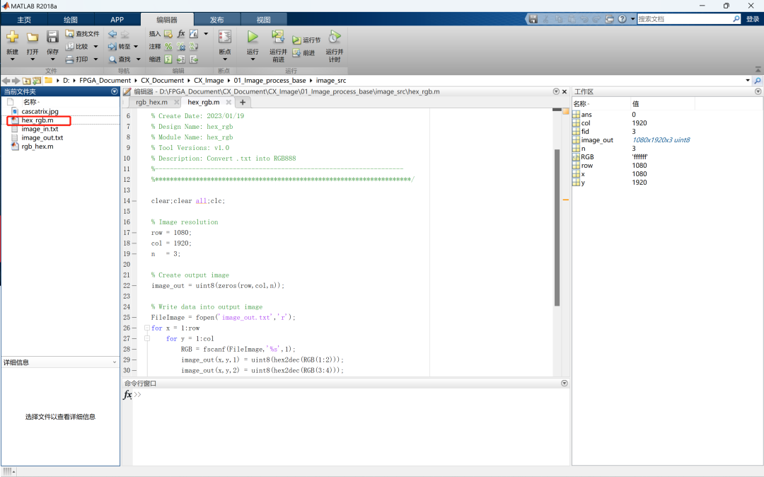
Matlab代码如下:
%**********************************************************************
% -------------------------------------------------------------------
% Company: Cascatrix
% Engineer: Carson
%
% Create Date: 2023/01/19
% Design Name: hex_rgb
% Module Name: hex_rgb
% Tool Versions: v1.0
% Description: Convert .txt into RGB888
%-------------------------------------------------------------------
%*********************************************************************/
clear;clear all;clc;
% Image resolution
row = 1080;
col = 1920;
n = 3;
% Create output image
image_out = uint8(zeros(row,col,n));
% Write data into output image
FileImage = fopen('image_out.txt','r');
for x = 1:row
for y = 1:col
RGB = fscanf(FileImage,'%s',1);
image_out(x,y,1) = uint8(hex2dec(RGB(1:2)));
image_out(x,y,2) = uint8(hex2dec(RGB(3:4)));
image_out(x,y,3) = uint8(hex2dec(RGB(5:6)));
end
end
fclose(FileImage);
% Show the output image
imshow(image_out),title('Image output');
% Create image in .jpg format
imwrite(image_out,'cascatrix_output.jpg');
运行结果:

生成cascatrix_output.jpg

03.coe格式图像仿真方法
通过读取.coe格式图像文件实现FPGA仿真步骤:
1. 利用Matlab通过图像获取.coe格式数据;
2. 通过操作ROM读取图像并处理生成.txt格式文件;
3. 利用Matlab转换显示Vivado处理后的.txt格式图像。
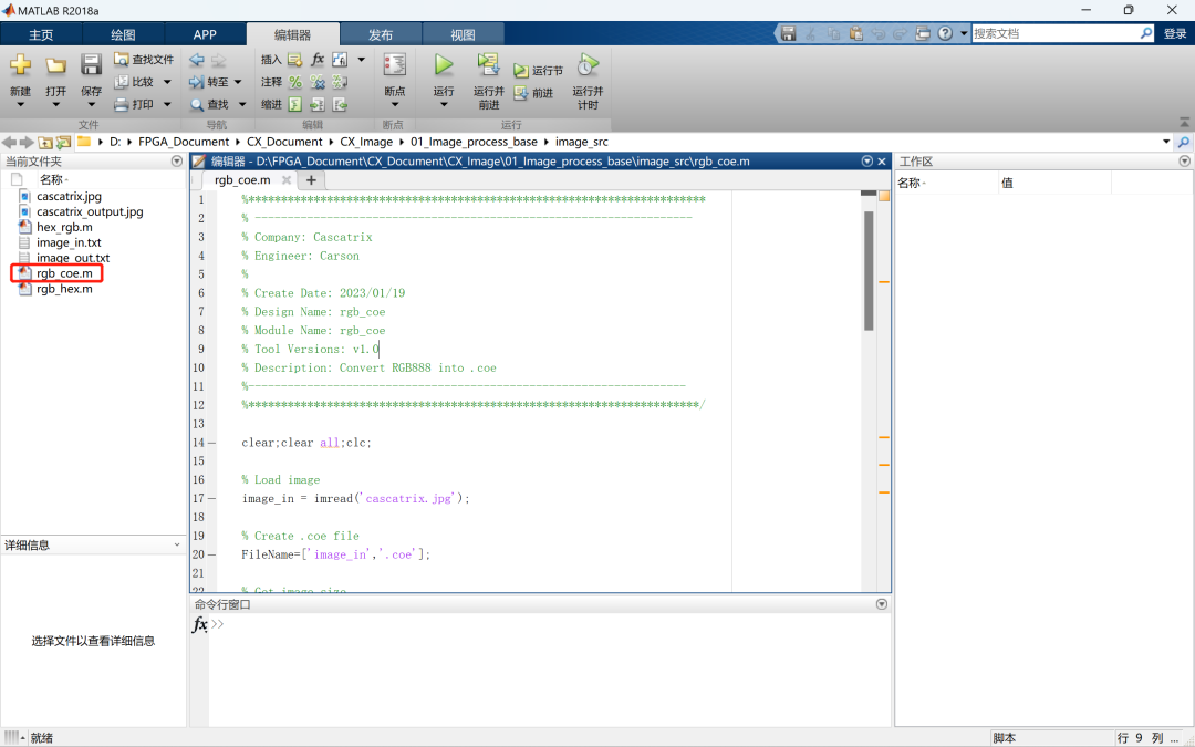
3.1 Matlab获取.coe文件
利用Matlab获取图像数据并生成.coe文件:
Matlab代码如下:
%**********************************************************************
% -------------------------------------------------------------------
% Company: Cascatrix
% Engineer: Carson
%
% Create Date: 2023/01/19
% Design Name: rgb_coe
% Module Name: rgb_coe
% Tool Versions: v1.0
% Description: Convert RGB888 into .coe
%-------------------------------------------------------------------
%*********************************************************************/
clear;clear all;clc;
% Load image
image_in = imread('cascatrix.jpg');
% Create .coe file
FileName=['image_in','.coe'];
% Get image size
[row,col,n] = size(image_in);
% Write image into image_in.coe
FileImage = fopen(FileName,'w');
% Format of image.coe
fprintf(FileImage,'memory_initialization_radix = 16; ');
fprintf(FileImage,'memory_initialization_vector = ');
for x = 1:row
for y = 1:col
image_r = dec2hex(image_in(x,y,1));
image_g = dec2hex(image_in(x,y,2));
image_b = dec2hex(image_in(x,y,3));
[r_row,r_col]=size(image_r);
[g_row,g_col]=size(image_g);
[b_row,b_col]=size(image_b);
if r_col == 1
image_r =['0',image_r];
elseif r_col == 0
image_r ='00';
end
if g_col == 1
image_g =['0',image_g];
elseif g_col == 0
image_g ='00';
end
if b_col == 1
image_b =['0',image_b];
elseif b_col == 0
image_b ='00';
end
if((x == row)&&(y == col))
image_hex=[image_r,image_g,image_b,';'];
else
image_hex=[image_r,image_g,image_b,','];
end
fprintf(FileImage,'%s ',image_hex);
end
end
fclose(FileImage);
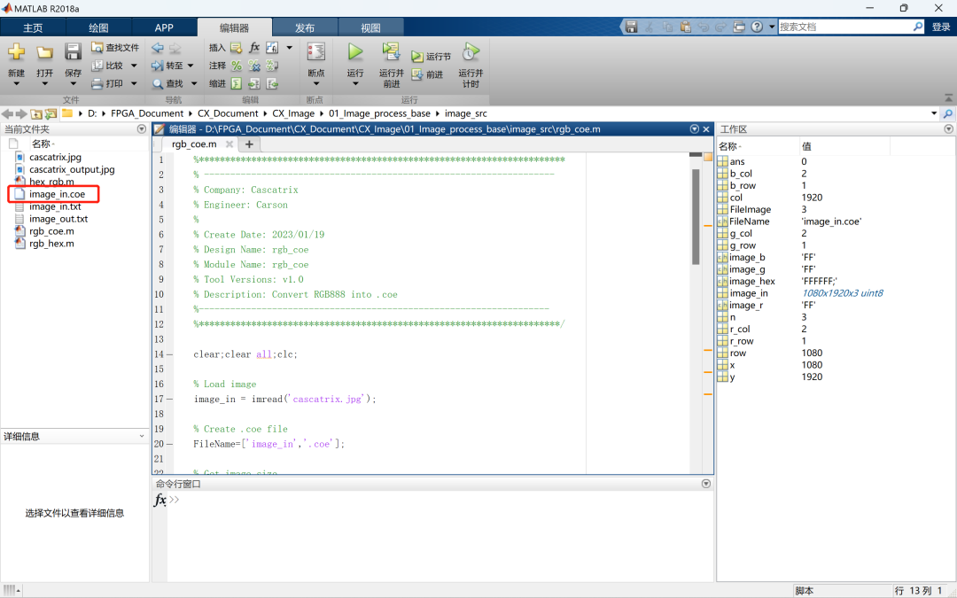
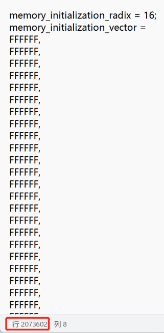
rgb_coe代码运行后生成.coe文件image_in.coe:
3.2 Vivado操作ROM
调用配置ROM IP核,通过操作ROM读取图像数据:
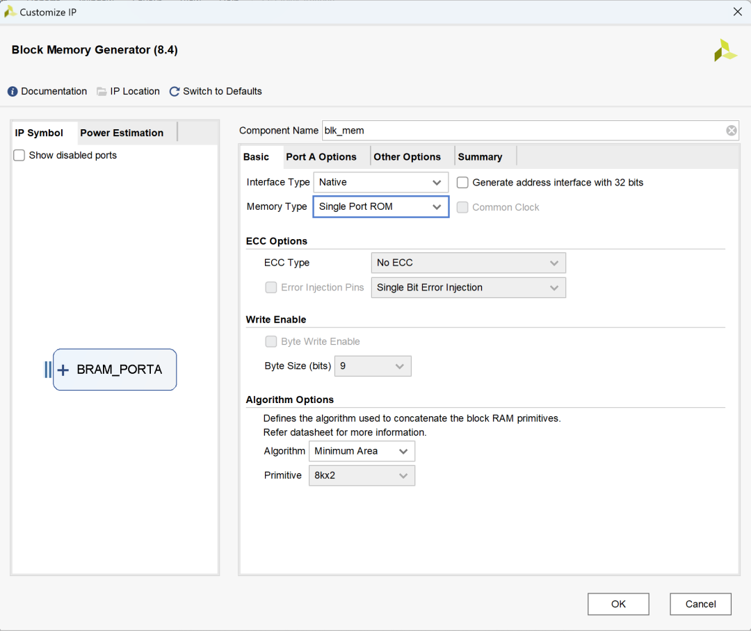
由于Vivado中ROM IP支持最大深度为1048576,无法完全存储1920×1080=2073600的图像数据,因此只能存储1280×720=921600的图像数据,上述.coe文件也应当由1280×720分辨率的图像生成:
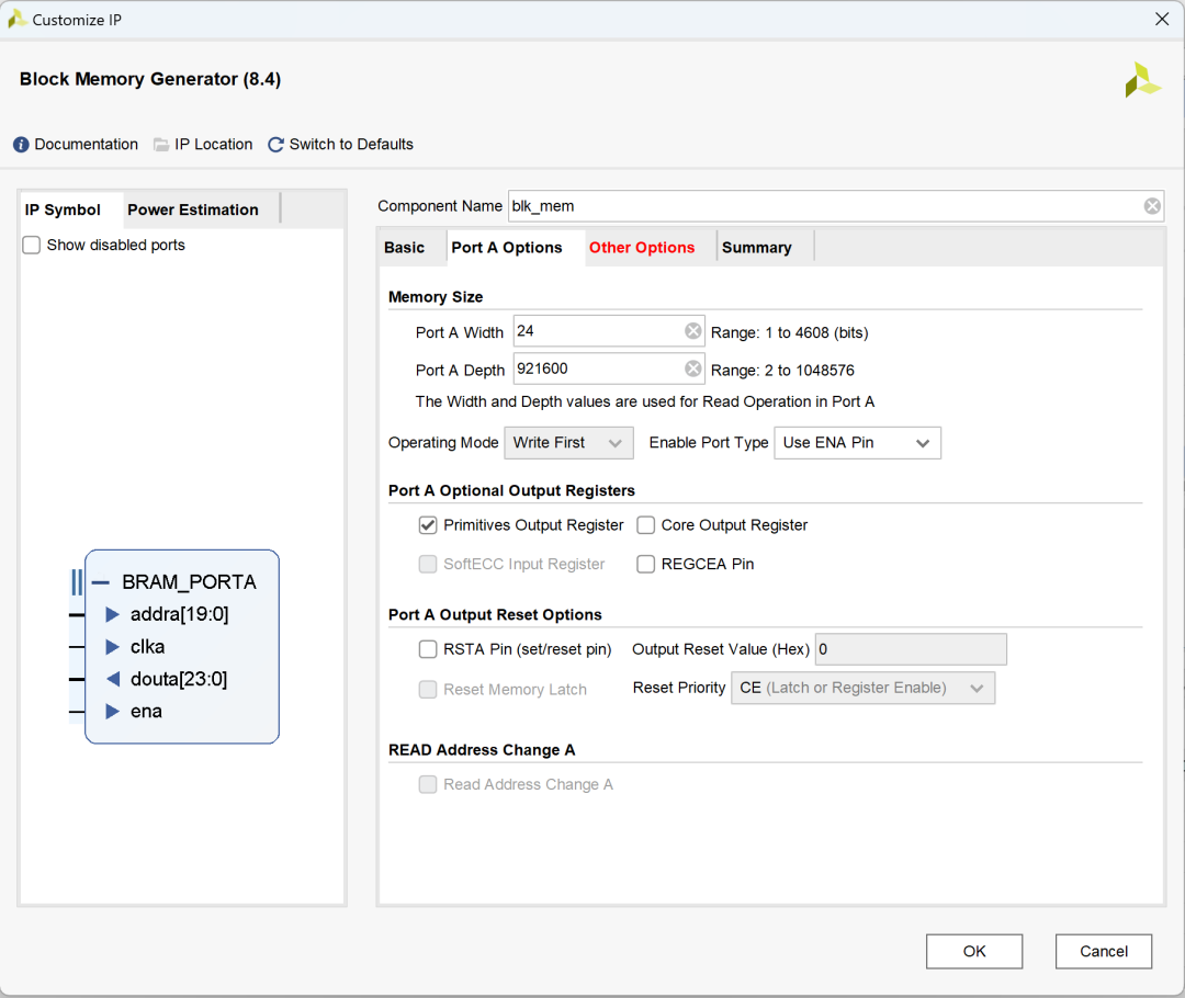
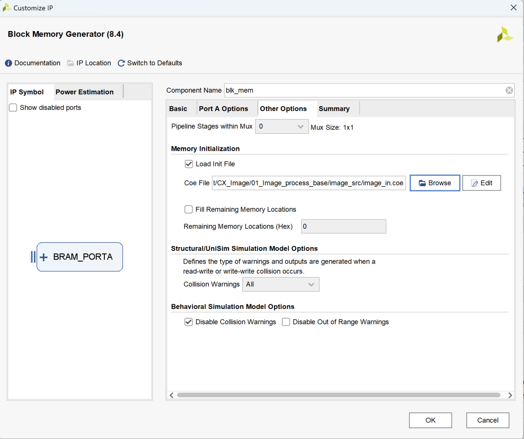
导入Matlab生成的image_in.coe文件为初始数据的,.coe文件内容一定要与上一步配置的接口宽度和深度相匹配,否则将会报错:
完成所有配置后,cx_image.v调用ROM并读取数据:
`timescale 1ns / 1ps
//////////////////////////////////////////////////////////////////////////////////
// Company: Cascatrix
// Engineer: Carson
//
// Create Date: 2023/01/15
// Design Name: Image_Base
// Module Name: cx_image
// Tool Versions: v1.0
// Description: Image read and generate display parameters
//
//////////////////////////////////////////////////////////////////////////////////
//`define PIXEL_1920_1080
//`define PIXEL_1680_1050
//`define PIXEL_1280_1024
`define PIXEL_1280_720
//`define PIXEL_1024_768
//`define PIXEL_800_600
//`define PIXEL_640_480
module cx_image(
inputwireclk,
outputreghs,
outputregvs,
outputwireen,
outputwire [23:0]data
);
//1920x1080 148.5Mhz
`ifdef PIXEL_1920_1080
parameter H_ACTIVE = 1920;// 行数据有效时间
parameter H_FRONT_PORCH = 88; // 行消隐前肩时间
parameter H_SYNC_TIME = 44; // 行同步信号时间
parameter H_BACK_PORCH = 148; // 行消隐后肩时间
parameter V_ACTIVE = 1080;// 列数据有效时间
parameter V_FRONT_PORCH = 4; // 列消隐前肩时间
parameter V_SYNC_TIME = 5; // 列同步信号时间
parameter V_BACK_PORCH = 36; // 列消隐后肩时间
`endif
//1680x1050 119Mhz
`ifdef PIXEL_1680_1050
parameter H_ACTIVE = 1680;// 行数据有效时间
parameter H_FRONT_PORCH = 48; // 行消隐前肩时间
parameter H_SYNC_TIME = 32; // 行同步信号时间
parameter H_BACK_PORCH = 80; // 行消隐后肩时间
parameter V_ACTIVE = 1050;// 列数据有效时间
parameter V_FRONT_PORCH = 3; // 列消隐前肩时间
parameter V_SYNC_TIME = 6; // 列同步信号时间
parameter V_BACK_PORCH = 21; // 列消隐后肩时间
`endif
//1280x1024 108Mhz
`ifdef PIXEL_1280_1024
parameter H_ACTIVE = 1280;// 行数据有效时间
parameter H_FRONT_PORCH = 48; // 行消隐前肩时间
parameter H_SYNC_TIME = 112; // 行同步信号时间
parameter H_BACK_PORCH = 248; // 行消隐后肩时间
parameter V_ACTIVE = 1024;// 列数据有效时间
parameter V_FRONT_PORCH = 1; // 列消隐前肩时间
parameter V_SYNC_TIME = 3; // 列同步信号时间
parameter V_BACK_PORCH = 38; // 列消隐后肩时间
`endif
//1280X720 74.25MHZ
`ifdef PIXEL_1280_720
parameter H_ACTIVE = 1280;// 行数据有效时间
parameter H_FRONT_PORCH = 110; // 行消隐前肩时间
parameter H_SYNC_TIME = 40; // 行同步信号时间
parameter H_BACK_PORCH = 220; // 行消隐后肩时间
parameter V_ACTIVE = 720; // 列数据有效时间
parameter V_FRONT_PORCH = 5; // 列消隐前肩时间
parameter V_SYNC_TIME = 5; // 列同步信号时间
parameter V_BACK_PORCH = 20; // 列消隐后肩时间
`endif
//1024x768 65Mhz
`ifdef PIXEL_1024_768
parameter H_ACTIVE = 1024;// 行数据有效时间
parameter H_FRONT_PORCH = 24; // 行消隐前肩时间
parameter H_SYNC_TIME = 136; // 行同步信号时间
parameter H_BACK_PORCH = 160; // 行消隐后肩时间
parameter V_ACTIVE = 768; // 列数据有效时间
parameter V_FRONT_PORCH = 3; // 列消隐前肩时间
parameter V_SYNC_TIME = 6; // 列同步信号时间
parameter V_BACK_PORCH = 29; // 列消隐后肩时间
`endif
//800x600 40Mhz
`ifdef PIXEL_800_600
parameter H_ACTIVE = 800;// 行数据有效时间
parameter H_FRONT_PORCH = 40 ;// 行消隐前肩时间
parameter H_SYNC_TIME = 128;// 行同步信号时间
parameter H_BACK_PORCH = 88 ;// 行消隐后肩时间
parameter V_ACTIVE = 600;// 列数据有效时间
parameter V_FRONT_PORCH = 1 ;// 列消隐前肩时间
parameter V_SYNC_TIME = 4 ;// 列同步信号时间
parameter V_BACK_PORCH = 23 ;// 列消隐后肩时间
`endif
//640x480 25.175Mhz
`ifdef PIXEL_640_480
parameter H_ACTIVE = 640; // 行数据有效时间
parameter H_FRONT_PORCH = 16 ; // 行消隐前肩时间
parameter H_SYNC_TIME = 96 ; // 行同步信号时间
parameter H_BACK_PORCH = 48 ; // 行消隐后肩时间
parameter V_ACTIVE = 480; // 列数据有效时间
parameter V_FRONT_PORCH = 10 ; // 列消隐前肩时间
parameter V_SYNC_TIME = 2 ; // 列同步信号时间
parameter V_BACK_PORCH = 33 ; // 列消隐后肩时间
`endif
parameter H_TOTAL_TIME = H_ACTIVE + H_FRONT_PORCH + H_SYNC_TIME + H_BACK_PORCH;
parameter V_TOTAL_TIME = V_ACTIVE + V_FRONT_PORCH + V_SYNC_TIME + V_BACK_PORCH;
reg h_act;
reg v_act;
reg [12:0] h_syn_cnt;
reg [12:0] v_syn_cnt;
reg [19:0] image_cnt;
// 有效数据控制
assign en = h_act & v_act;
// 行扫描计数器
always@(posedge clk)
begin
if(h_syn_cnt == H_TOTAL_TIME - 1)
h_syn_cnt <= 13'b0;
else
h_syn_cnt <= h_syn_cnt + 1'b1;
end
// 列扫描计数器
always@(posedge clk)
begin
if(h_syn_cnt == H_TOTAL_TIME - 1)
begin
if(v_syn_cnt == V_TOTAL_TIME-1)
v_syn_cnt <= 13'b0;
else
v_syn_cnt <= v_syn_cnt + 1'b1;
end
end
// 行同步控制
always@(posedge clk)
begin
if(h_syn_cnt < H_SYNC_TIME)
hs <= 1'b0;
else
hs <= 1'b1;
end
// 场同步控制
always@(posedge clk)
begin
if(v_syn_cnt < V_SYNC_TIME)
vs <= 1'b0;
else
vs <= 1'b1;
end
// 行有效控制
always@(posedge clk)
begin
if(h_syn_cnt == H_SYNC_TIME + H_BACK_PORCH - 1)
h_act = 1'b1;
else if(h_syn_cnt == H_SYNC_TIME + H_BACK_PORCH + H_ACTIVE - 1)
h_act = 1'b0;
end
// 列有效控制
always@(posedge clk)
begin
if(v_syn_cnt == V_SYNC_TIME + V_BACK_PORCH - 1 && h_syn_cnt == 0)
v_act = 1'b1;
else if(v_syn_cnt == V_SYNC_TIME + V_BACK_PORCH + V_ACTIVE - 1 && h_syn_cnt == 0)
v_act = 1'b0;
end
// 像素数计数器
always@(posedge clk)
begin
if(image_cnt == H_ACTIVE*V_ACTIVE - 1)
image_cnt <= 20'b0;
else if(h_act & v_act)
image_cnt <= image_cnt + 1'b1;
end
// 调用ROM IP
blk_mem inst_blk_mem
(
.clka (clk),
.ena (h_act & v_act),
.addra (image_cnt),
.douta (data)
);
endmodule
仿真文件仍沿用cx_tb.v,但图像分辨率应改为1280×720,生成image_out.txt文件与仿真波形:

3.3 Matlab显示.txt文件
采用2.3中.txt文件转图像的Matlab代码hex_rgb.m,同样可以得到图像:


04图像存储模块仿真方法
通过读取.coe格式图像文件实现FPGA仿真步骤:
1. 利用Matlab生成图像存储模块.v文件;
2. 通过VIVADO读取图像并处理生成.txt格式文件;
3. 利用Matlab转换显示Vivado处理后的.txt格式图像。
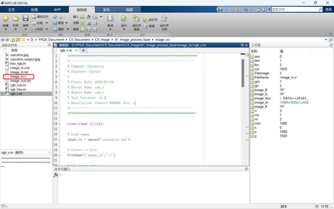
4.1 Matlab生成.v文件
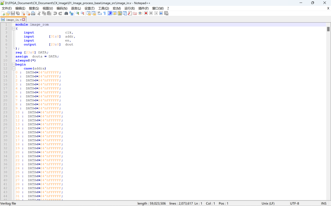
利用Matlab获取图像数据并生成.v文件:
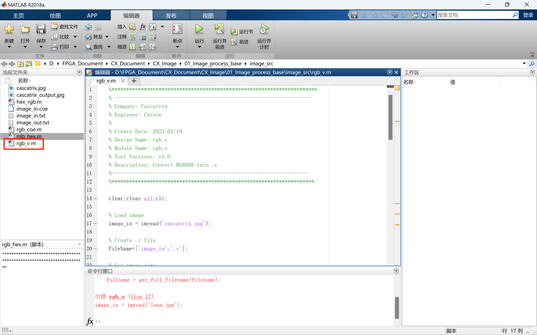
Matlab代码如下:
%**********************************************************************
% -------------------------------------------------------------------
% Company: Cascatrix
% Engineer: Carson
%
% Create Date: 2023/01/19
% Design Name: rgb_v
% Module Name: rgb_v
% Tool Versions: v1.0
% Description: Convert RGB888 into .v
%-------------------------------------------------------------------
%*********************************************************************/
clear;clear all;clc;
% Load image
image_in = imread('cascatrix.jpg');
% Create .v file
FileName=['image_in','.v'];
% Get image size
[row,col,n] = size(image_in);
% Write image into image_in.v
FileImage = fopen(FileName,'w');
% Format of image.coe
fprintf(FileImage,'module image_rom ');
fprintf(FileImage,'( ');
fprintf(FileImage,'input clk, ');
fprintf(FileImage,'input[31:0]addr, ');
fprintf(FileImage,'inputen, ');
fprintf(FileImage,'output[23:0]dout ');
fprintf(FileImage,'); ');
fprintf(FileImage,'reg [23:0] DATA; ');
fprintf(FileImage,'assigndouta = DATA; ');
fprintf(FileImage,'always@(*) ');
fprintf(FileImage,'begin ');
fprintf(FileImage,'case(addra) ');
s=0;
for x = 1:row
for y = 1:col
image_R = dec2hex(image_in(x,y,1));
image_G = dec2hex(image_in(x,y,2));
image_B = dec2hex(image_in(x,y,3));
[rm,rn]=size(image_R);
[gm,gn]=size(image_G);
[bm,bn]=size(image_B);
if rn == 1
image_R =['0',image_R];
elseif rn == 0
image_R ='00';
end
if gn == 1
image_G =['0',image_G];
elseif gn == 0
image_G ='00';
end
if bn == 1
image_B =['0',image_B];
elseif bn == 0
image_B ='00';
end
image_hex=[': DATA<=24','''','h',image_R,image_G,image_B,';'];
fprintf(FileImage,'%d %s ',(x-1)*col + y -1,image_hex);
end
end
fprintf(FileImage,' default: DATA<= 0; ');
fprintf(FileImage,'endcase ');
fprintf(FileImage,'end ');
fprintf(FileImage,'endmodule ');
fclose(FileImage);
rgb_v代码运行后生成.v文件image_in.v:
4.2 Vivado读取与处理
将生成的图像存储image.v模块在cx_image调用:
`timescale 1ns / 1ps
//////////////////////////////////////////////////////////////////////////////////
// Company: Cascatrix
// Engineer: Carson
//
// Create Date: 2023/01/15
// Design Name: Image_Base
// Module Name: cx_image
// Tool Versions: v1.0
// Description: Image read and generate display parameters
//
//////////////////////////////////////////////////////////////////////////////////
`define PIXEL_1920_1080
//`define PIXEL_1680_1050
//`define PIXEL_1280_1024
//`define PIXEL_1280_720
//`define PIXEL_1024_768
//`define PIXEL_800_600
//`define PIXEL_640_480
module cx_image(
inputwireclk,
outputreghs,
outputregvs,
outputwireen,
outputwire [23:0]data
);
//1920x1080 148.5Mhz
`ifdef PIXEL_1920_1080
parameter H_ACTIVE = 1920;// 行数据有效时间
parameter H_FRONT_PORCH = 88; // 行消隐前肩时间
parameter H_SYNC_TIME = 44; // 行同步信号时间
parameter H_BACK_PORCH = 148; // 行消隐后肩时间
parameter V_ACTIVE = 1080;// 列数据有效时间
parameter V_FRONT_PORCH = 4; // 列消隐前肩时间
parameter V_SYNC_TIME = 5; // 列同步信号时间
parameter V_BACK_PORCH = 36; // 列消隐后肩时间
`endif
//1680x1050 119Mhz
`ifdef PIXEL_1680_1050
parameter H_ACTIVE = 1680;// 行数据有效时间
parameter H_FRONT_PORCH = 48; // 行消隐前肩时间
parameter H_SYNC_TIME = 32; // 行同步信号时间
parameter H_BACK_PORCH = 80; // 行消隐后肩时间
parameter V_ACTIVE = 1050;// 列数据有效时间
parameter V_FRONT_PORCH = 3; // 列消隐前肩时间
parameter V_SYNC_TIME = 6; // 列同步信号时间
parameter V_BACK_PORCH = 21; // 列消隐后肩时间
`endif
//1280x1024 108Mhz
`ifdef PIXEL_1280_1024
parameter H_ACTIVE = 1280;// 行数据有效时间
parameter H_FRONT_PORCH = 48; // 行消隐前肩时间
parameter H_SYNC_TIME = 112; // 行同步信号时间
parameter H_BACK_PORCH = 248; // 行消隐后肩时间
parameter V_ACTIVE = 1024;// 列数据有效时间
parameter V_FRONT_PORCH = 1; // 列消隐前肩时间
parameter V_SYNC_TIME = 3; // 列同步信号时间
parameter V_BACK_PORCH = 38; // 列消隐后肩时间
`endif
//1280X720 74.25MHZ
`ifdef PIXEL_1280_720
parameter H_ACTIVE = 1280;// 行数据有效时间
parameter H_FRONT_PORCH = 110; // 行消隐前肩时间
parameter H_SYNC_TIME = 40; // 行同步信号时间
parameter H_BACK_PORCH = 220; // 行消隐后肩时间
parameter V_ACTIVE = 720; // 列数据有效时间
parameter V_FRONT_PORCH = 5; // 列消隐前肩时间
parameter V_SYNC_TIME = 5; // 列同步信号时间
parameter V_BACK_PORCH = 20; // 列消隐后肩时间
`endif
//1024x768 65Mhz
`ifdef PIXEL_1024_768
parameter H_ACTIVE = 1024;// 行数据有效时间
parameter H_FRONT_PORCH = 24; // 行消隐前肩时间
parameter H_SYNC_TIME = 136; // 行同步信号时间
parameter H_BACK_PORCH = 160; // 行消隐后肩时间
parameter V_ACTIVE = 768; // 列数据有效时间
parameter V_FRONT_PORCH = 3; // 列消隐前肩时间
parameter V_SYNC_TIME = 6; // 列同步信号时间
parameter V_BACK_PORCH = 29; // 列消隐后肩时间
`endif
//800x600 40Mhz
`ifdef PIXEL_800_600
parameter H_ACTIVE = 800;// 行数据有效时间
parameter H_FRONT_PORCH = 40 ;// 行消隐前肩时间
parameter H_SYNC_TIME = 128;// 行同步信号时间
parameter H_BACK_PORCH = 88 ;// 行消隐后肩时间
parameter V_ACTIVE = 600;// 列数据有效时间
parameter V_FRONT_PORCH = 1 ;// 列消隐前肩时间
parameter V_SYNC_TIME = 4 ;// 列同步信号时间
parameter V_BACK_PORCH = 23 ;// 列消隐后肩时间
`endif
//640x480 25.175Mhz
`ifdef PIXEL_640_480
parameter H_ACTIVE = 640; // 行数据有效时间
parameter H_FRONT_PORCH = 16 ; // 行消隐前肩时间
parameter H_SYNC_TIME = 96 ; // 行同步信号时间
parameter H_BACK_PORCH = 48 ; // 行消隐后肩时间
parameter V_ACTIVE = 480; // 列数据有效时间
parameter V_FRONT_PORCH = 10 ; // 列消隐前肩时间
parameter V_SYNC_TIME = 2 ; // 列同步信号时间
parameter V_BACK_PORCH = 33 ; // 列消隐后肩时间
`endif
parameter H_TOTAL_TIME = H_ACTIVE + H_FRONT_PORCH + H_SYNC_TIME + H_BACK_PORCH;
parameter V_TOTAL_TIME = V_ACTIVE + V_FRONT_PORCH + V_SYNC_TIME + V_BACK_PORCH;
reg h_act;
reg v_act;
reg [12:0] h_syn_cnt;
reg [12:0] v_syn_cnt;
reg [31:0] image_cnt;
// 有效数据控制
assign en = h_act & v_act;
// 行扫描计数器
always@(posedge clk)
begin
if(h_syn_cnt == H_TOTAL_TIME - 1)
h_syn_cnt <= 13'b0;
else
h_syn_cnt <= h_syn_cnt + 1'b1;
end
// 列扫描计数器
always@(posedge clk)
begin
if(h_syn_cnt == H_TOTAL_TIME - 1)
begin
if(v_syn_cnt == V_TOTAL_TIME-1)
v_syn_cnt <= 13'b0;
else
v_syn_cnt <= v_syn_cnt + 1'b1;
end
end
// 行同步控制
always@(posedge clk)
begin
if(h_syn_cnt < H_SYNC_TIME)
hs <= 1'b0;
else
hs <= 1'b1;
end
// 场同步控制
always@(posedge clk)
begin
if(v_syn_cnt < V_SYNC_TIME)
vs <= 1'b0;
else
vs <= 1'b1;
end
// 行有效控制
always@(posedge clk)
begin
if(h_syn_cnt == H_SYNC_TIME + H_BACK_PORCH - 1)
h_act = 1'b1;
else if(h_syn_cnt == H_SYNC_TIME + H_BACK_PORCH + H_ACTIVE - 1)
h_act = 1'b0;
end
// 列有效控制
always@(posedge clk)
begin
if(v_syn_cnt == V_SYNC_TIME + V_BACK_PORCH - 1 && h_syn_cnt == 0)
v_act = 1'b1;
else if(v_syn_cnt == V_SYNC_TIME + V_BACK_PORCH + V_ACTIVE - 1 && h_syn_cnt == 0)
v_act = 1'b0;
end
// 像素数计数器
always@(posedge clk)
begin
if(image_cnt == H_ACTIVE*V_ACTIVE - 1)
image_cnt <= 32’b0;
else if(h_act & v_act)
image_cnt <= image_cnt + 1'b1;
end
// 图像像素值存储模块
image inst_rom_image
(
.clk (clk),
.en (h_act & v_act),
.addr (image_cnt),
.dout (data)
);
endmodule
仿真文件仍采用cx_tb.v,生成image_out.txt文件与仿真波形:

4.3 Matlab显示.txt文件
采用2.3中.txt文件转图像的Matlab代码hex_rgb.m,同样可以得到图像:


-
FPGA
+关注
关注
1631文章
21808浏览量
606808 -
matlab
+关注
关注
186文章
2983浏览量
231258 -
Verilog
+关注
关注
28文章
1355浏览量
110545 -
数字图像处理
+关注
关注
7文章
103浏览量
18991 -
图像仿真
+关注
关注
0文章
2浏览量
5240
原文标题:FPGA数字图像处理仿真方法
文章出处:【微信号:Carlinx FPGA,微信公众号:Carlinx FPGA】欢迎添加关注!文章转载请注明出处。
发布评论请先 登录
相关推荐
数字图像处理平台系统方案详解


 FPGA数字图像处理仿真方法


评论