低侧电流测试
低侧电流检测可能是最常见的电流检测技术。主要原因是它既不需要高性能PWM抑制电流检测放大器(如在线检测放大器),也不需要支持高压的放大器(如高侧放大器)。
采样电阻始终置于低侧MOSFET和地之间,确保放大器的端子上始终具有非常低的电压。这种方法的主要缺点是,由于只有相应的低侧mosfet开启时,通过采样电阻的电流才是相电流,而我们只能在这些时刻测量到相电流。PWM频率通常为20至50 kHz,这意味着低侧MOSFET每秒开关20000至50000次,因此PWM设置和ADC采集之间的同步非常重要。
目前这个在开发中。
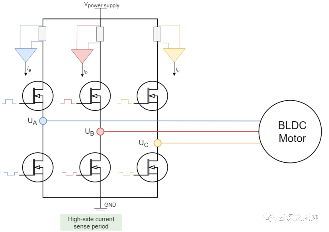
这个是高测测量一般也不用
https://www.ti.com.cn/product/cn/INA240
https://www.elecfans.com/analog/202007151246626.html
https://zhuanlan.zhihu.com/p/401573207
https://www.sohu.com/a/439655421_468638
https://baijiahao.baidu.com/s?id=1753450617334241521&wfr=spider&for=pc
https://m.elecfans.com/article/1107269.html
https://www.elecfans.com/d/1412716.html
// IN1     pwm1    9  27
// IN2     pwm2    6  26
// IN3     pwm3    5  25
// INH1   enable1  8  12
// INH2   enable2  7  13
// INH3   enable3  4  14
// in-line current sense - phase 1/A 35
// in-line current sense - phase 1/C 34


#include


class LowPassFilte
{
public:
    LowPassFilte(float Tf); // 低通滤波器时间常量
    ~LowPassFilte() = default;
    float operator()(float x);
    float Tf; //!< 低通滤波器时间常量
protected:
    unsigned long timestamp_prev; //!< 上次执行时间戳
    float y_prev;                 //!< 经过上次执行后过滤到的值
};


LowPassFilte::LowPassFilte(float time_constant)
    : Tf(time_constant), y_prev(0.0f)
{
    timestamp_prev = micros();
}


float LowPassFilte::operator()(float x)
{
    unsigned long timestamp = micros();
    float dt = (timestamp - timestamp_prev) * 1e-6f;


    if (dt < 0.0f || dt > 0.5f)
        dt = 1e-3f;


    float alpha = Tf / (Tf + dt);
    float y = alpha * y_prev + (1.0f - alpha) * x;


    y_prev = y;
    timestamp_prev = timestamp;
    return y;
}


LowPassFilte LF_a(0.01); // 原始数据滤波器
LowPassFilte LF_b(0.01); // A相电流滤波器
LowPassFilte LF_c(0.01); // C相电流滤波器


// AS5600编码器支持spi,iic和模拟量三种数据传输方式,这里用iic(同时也是最常用的方式)
//  magnetic sensor instance - I2C
MagneticSensorI2C sensor = MagneticSensorI2C(AS5600_I2C);
TwoWire I2Cone = TwoWire(0);


// BLDC motor & driver instance
BLDCMotor motor = BLDCMotor(11);
BLDCDriver3PWM driver = BLDCDriver3PWM(27, 26, 25, 12, 13, 14);


InlineCurrentSense Cs_motor(0.001, 50.0, 35, 36, 34);


// voltage set point variable
float target_voltage = 5.0;
// instantiate the commander
Commander command = Commander(Serial);
void doTarget(char *cmd)
{
    command.scalar(&target_voltage, cmd);
}


void setup()
{
    // initialise magnetic sensor hardware
    I2Cone.begin(18, 5, 400000);
    sensor.init(&I2Cone);
    // link the motor to the sensor
    motor.linkSensor(&sensor);


    // power supply voltage
    driver.voltage_power_supply = 12;
    driver.init();
    motor.linkDriver(&driver);


    // aligning voltage
    motor.voltage_sensor_align = 5;
    // choose FOC modulation (optional)
    motor.foc_modulation = FOCModulationType::SpaceVectorPWM;
    // set motion control loop to be used
    motor.controller = MotionControlType::torque;


    // use monitoring with serial
    Serial.begin(115200);
    // comment out if not needed
    motor.useMonitoring(Serial);


    // initialize motor
    motor.init();
    // align sensor and start FOC
    motor.initFOC();


    // add target command T
    command.add('T', doTarget, "target voltage");


    Serial.println(F("Motor ready."));
    Serial.println(F("Set the target voltage using serial terminal:"));
    _delay(1000);


    Cs_motor.init();
}


void loop()
{


    // main FOC algorithm function
    // the faster you run this function the better
    // Arduino UNO loop  ~1kHz
    // Bluepill loop ~10kHz
    motor.loopFOC();
    // Motion control function
    // velocity, position or voltage (defined in motor.controller)
    // this function can be run at much lower frequency than loopFOC() function
    // You can also use motor.move() and set the motor.target in the code
    motor.move(target_voltage);


    // Cs_motor.getPhaseCurrents();
    Serial.print(LF_b((Cs_motor.getPhaseCurrents()).a));
    Serial.print(",");
    Serial.println(LF_c((Cs_motor.getPhaseCurrents()).c));


    //  Serial.print(LF_a(analogRead(35)));
    //  Serial.print(",");
    //  Serial.print(LF_b((3.3 * ((float)analogRead(35) - 1930) / 4096.0) * 20.0));
    //  Serial.print(",");
    //  Serial.println(LF_c((-3.3 * ((float)analogRead(34) - 1930) / 4096.0) * 20.0));


    // user communication
    command.run();
}
声明:本文内容及配图由入驻作者撰写或者入驻合作网站授权转载。文章观点仅代表作者本人,不代表电子发烧友网立场。文章及其配图仅供工程师学习之用,如有内容侵权或者其他违规问题,请联系本站处理。
举报投诉
-
开关
+关注
关注
19文章
3138浏览量
93725 -
IGBT
+关注
关注
1267文章
3802浏览量
249296 -
MOS
+关注
关注
32文章
1275浏览量
93896 -
功率器件
+关注
关注
41文章
1773浏览量
90495
发布评论请先 登录
相关推荐
步进电机相电流怎么测
的重要性 步进电机作为一种重要的自动化设备,广泛应用于各种工业和民用领域。相电流是步进电机驱动的核心参数之一,直接影响电机的力矩、速度和精度。因此,准确测量步进电机相电流对于确保电机正常运行、提高生产效率、优
无刷电机相电流比母线电流大?
三相无刷直流电机,带三相线性霍尔反馈电机转子位置,就是可以根据霍尔的电压来控制PWM占空比从而生成正弦波电流,驱动电路使用3相H桥双极驱动,使用三组6路互补SPWM控制,在
发表于 01-19 10:42
什么是相电流和线电流
三角连接方式:如果3个线电流与3个相电流相对称,那么线电流等于√3*相电流;如果是非对称的情况,那就需要计算各相负载的性质,算出电流和电压的
发表于 03-11 10:43
•19.5w次阅读
SimpleFOC -foc电流-力矩控制代码
#include #include // 无刷直流电机及驱动器实例BLDCMotor motor = BLDCMotor(1
发表于 12-16 16:51
•14次下载

SimpleFOC -位置控制代码
#include #include // 无刷直流电机及驱动器实例BLDCMotor motor = BLDCMotor(6
发表于 01-14 12:56
•6次下载

SimpleFOC之多路PWM驱动,相电流监测1
开关元器件的和严格意义并不是相同的。IGBT,MOS并不是理想开关器件,其开通时间和关断时间不是严格一致的,如果两端有电压,将导致直流电源短路,损坏桥臂功率器件,称之为“桥臂直通”。所以在驱动开关元器件门极的时候需要增加一段延时,确保另一个开关管完全关断之后再去打开这个开关元器件,通常存在两种情况;

怎么区分相电流与线电流的区别
相电流与线电流是电力系统中的两个重要概念,它们在电路分析和电力系统设计中扮演着关键角色。本文将介绍相电流与线电流的区别。 一、相电流与线
相电流和线电流的相位关系
在电力系统中,电流的相位关系对于系统的正常运行和设备的安全使用至关重要。本文将探讨相电流和线电流的相位关系,以及它们在电力系统中的作用和影响。 一、相电流和线


 SimpleFOC之多路PWM驱动,相电流监测2


评论