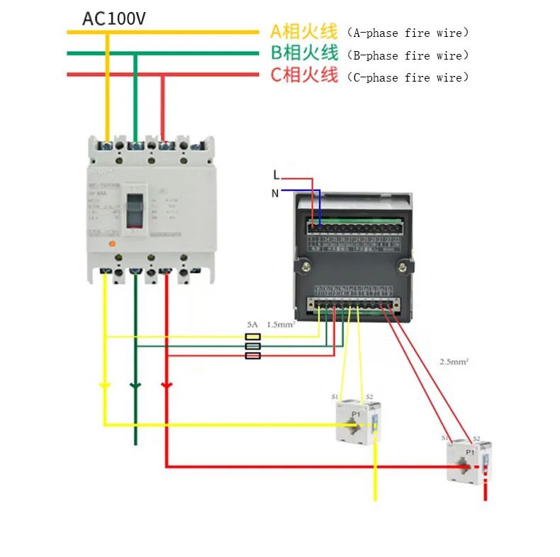
三相三线图
Three-phase three-wire diagram
1、端子数目1和2为辅助电源: 如上图所示,连接相电压220v 输入。其中,辅助电源的火线装有5A 熔断器,中性线直接连接到零线铜条上。
Terminal numbers 1 and 2 are auxiliary power supply: as shown in the figure above, connect the phase voltage 220V input. Among them, the fire wire of the auxiliary power supply is installed 5A fuse, the neutral wire is directly connected to the zero line copper bar.
2、电压接线:在三相三线的情况下,电压信号端子以V型接线方式连接,11连接到A相电压,12连接到B相电压,13连接到C电压,14连接到B相电压,电压线为1.5平方BVR多芯硬线,带电线连接到仪表。他们之间需要安装一个5A保险丝。Voltage wiring:In the case of three-phase three-wire, the voltage signal terminals are connected in V-shaped wiring mode, 11 is connected to A-phase voltage, 12 is connected to B-phase voltage, 13 is connected to C voltage and 14 is connected to B-phase voltage ; the voltage wire is a 1.5 square BVR multi-core hard wire, and the live wire is connected to the meter. A 5A fuse needs to be installed between them.
3、电流接线:在三相三线的情况下,电流信号端子连接成V形,变压器的一次电流从P1侧流向 P2侧; 互感器的输出 S1连接到第4端子,S2连接到第5端子,C互感器S1连接到第8端子,S2连接到9个端子,其中带 * 的端子连接到变压器的 S1端子,电流采用2.5平方BVR多芯硬线。
Current wiring:In the case of three-phase three-wire, the current signal terminals are connected in a V-shape, and the primary current of the transformer flows from the P1 side to the P2 side ; the output S1 of the A mutual inductor is connected to the 4th terminal, S2 is connected to the 5th terminal, the C mutual inductor S1 is connected to the 8th terminal, and S2 Connect to 9 terminals, of which the terminal with * corresponds to the S1 terminal of the transformer ; the current wire uses a 2.5 square BVR multi-core hard wire.
4、通信终端:RS485 (A+, B-) A 连接到端口21,B连接到端口22,使用RVSP2*1.0平方芯双绞线屏蔽柔性导线。Communication terminals: RS485 (A+, B-) A is connected to port 21, B is connected to port 22, use RVSP2*1.0 square Core twisted pair shielded flexible wire.
5、一定要按照说明接线,错误的接线会导致测量不准确。仪表的侧面标签上有接线图。
Be sure to wire according to the instructions, wrong connection will lead to inaccurate measurement. There are wiring diagrams on the side labels of the meter.
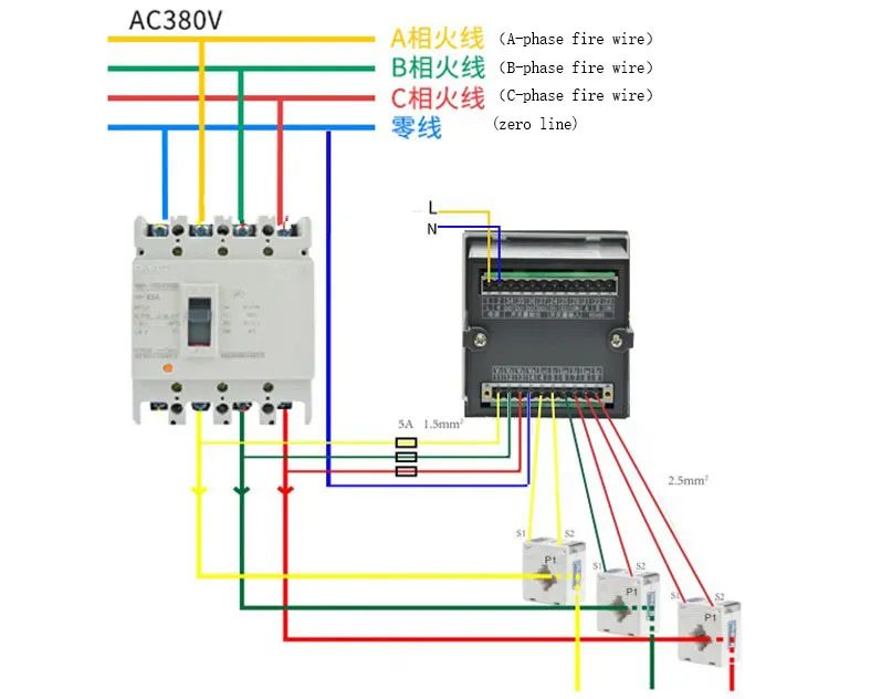
三相四线图
Three-phase four-wire diagram
1、端子数目1和2为辅助电源: 如上图所示,连接相电压220V输入。辅助电源装有5A保险丝,连接到零排。其中,中性线的火线是直接。
Terminal numbers 1 and 2 are auxiliary power supply: as shown in the figureabove, connect the phase voltage 220V input. auxiliary power supply is installed 5A fuse, connected to the zero row.
2、电压接线:在三相四线制情况下,电压信号端子以Y型接线方式连接,分别对应于11相电压、12相电压、13至C电压和14至N线; 电压线采用1.5平方BVR多芯硬线,通电线与仪表之间应安装5A熔断器。
Voltage wiring:In the case of three-phase four-wire, the voltage signal terminals are connected in a Y-shaped wiring mode, respectively corresponding to 11 connected to A-phase voltage, 12 to B-phase voltage, 13 to C voltage and 14 to N line; the voltage line uses a 1.5 square BVR multi-core hard wire , a 5A fuse should be installed between the live wire and the meter.
3、电流接线: 在三相三线的情况下,电流信号端子连接成V形,变压器的一次电流从P1侧流向P2侧; 互感器的输出S1连接到第4端子,S2连接到第5端子,C互感器 s1连接到第8端子,S2连接到9个端子,其中带 * 的端子连接到变压器的S1端子,电流采用2.5平方BVR多芯硬线。
Current wiring:In the case of three-phase three-wire, the current signal terminals areconnected in a V-shape, and the primary current of the transformer flows from the P1 side to the P2 side; the output S1 of the A mutual inductor is connected to the 4th terminal, S2 is connected to the 5th terminal, the C mutual inductor S1 is connected to the 8th terminal, and S2 Connect to 9 terminals, of which the terminal with * corresponds to the S1 terminal of the transformer ; the current wire uses a 2.5 square BVR multi-core hard wire.
4、通信终端:RS485 (A+, B-) A 连接到端口21,B连接到端口22,使用 RVSP2*1.0平方多核双绞线屏蔽软线。
Communication terminals: RS485 (A+, B-) A is connected to port 21, B is connected to port 22, use RVSP2*1.0 square multi-core twisted pair shielded flexible wire.
5、一定要按照说明接线,错误的接线会导致测量不准确。仪表的侧面标签上有接线图。
Be sure to wire according to the instructions, wrong connection will lead to inaccurate measurement. There are wiring diagrams on the side labels of the meter.
-
多功能
+关注
关注
0文章
85浏览量
19119 -
接线
+关注
关注
29文章
722浏览量
33216
发布评论请先 登录
相关推荐
分布式光伏380v并网交流电能计量多功能仪表 IEC标准
什么是三相多功能电力仪表?有什么作用?
三相多功能用电检查仪的接线说明——每日了解电力知识

多功能数显表的功能特点有哪些?
安科瑞PZ42-E4系列三相智能多功能电测仪表
三相液晶多功能电力仪表 BE151系列说明书
三相数显多功能电力仪表BE150系列说明书
安科瑞多功能电力仪表在莫桑比克某农场的应用
ACRELADL系列多功能电能表在迪拜大厦EMS中的应用


 多功能仪表接线说明Acrel Multi-function Meter Wiring Instruction


评论