 瑞萨e2studio----串口获取数据通过SPI存储于W25Q128外部flash

1.概述
本篇文章主要介绍如何使用e2studio对瑞萨进行spi配置,同时移植stm32上的W25Q128到瑞萨上,同时通过对该FLASH进行读写操作,验证是否正确。
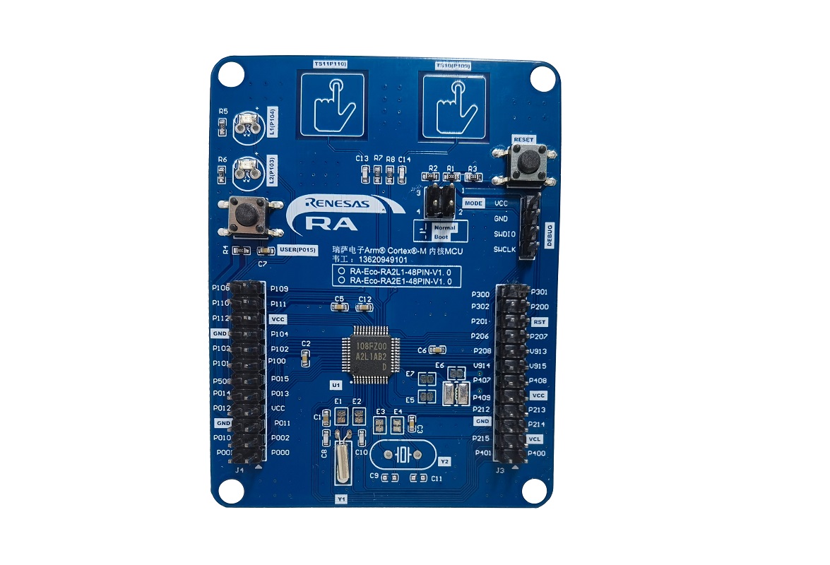
2.硬件准备
首先需要准备一个开发板,这里我准备的是芯片型号 R7FA2L1AB2DFL 的开发板。
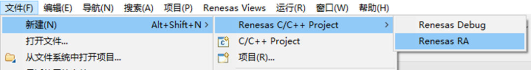
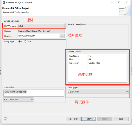
3.新建工程
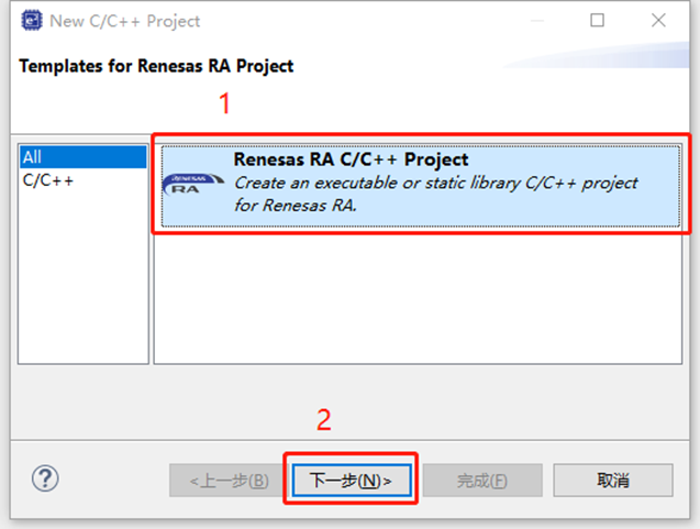
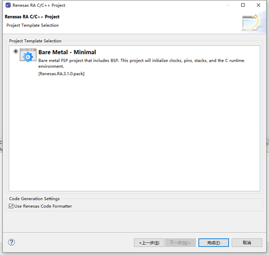
4.工程模板
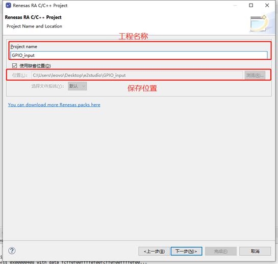
5.保存工程路径
6.芯片配置
本文中使用R7FA2L1AB2DFL来进行演示。
7
7.工程模板选择
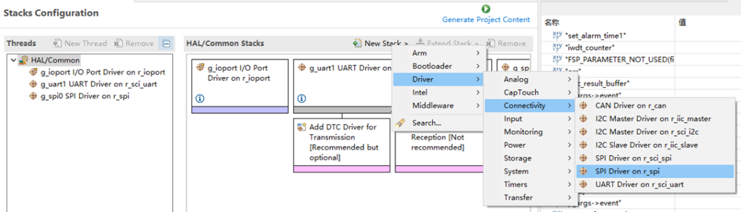
8.SPI配置
点击Stacks->New Stack->Driver->Connectivity->SPI Driver on r_spi。
9.SPI属性配置
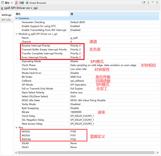
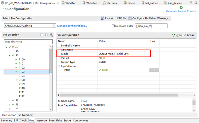
10.片选CS管脚设置
设置P103管脚为输出管脚,作为CS片选。
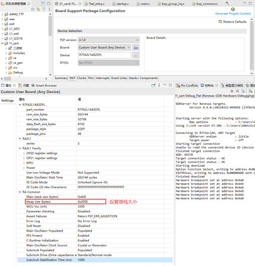
11.设置E2STUDIO堆栈
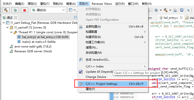
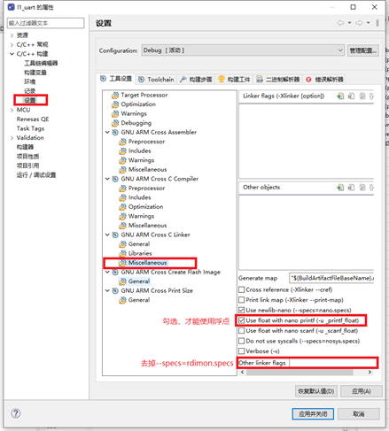
12.e2studio的重定向printf设置
C++ 构建->设置->GNU ARM Cross C Linker->Miscellaneous去掉Other linker flags中的 “--specs=rdimon.specs”
13.printf输出重定向到串口
打印最常用的方法是printf,所以要解决的问题是将printf的输出重定向到串口,然后通过串口将数据发送出去。
注意一定要加上头文件#include
#ifdef __GNUC__                                 //串口重定向
    #define PUTCHAR_PROTOTYPE int __io_putchar(int ch)
#else
    #define PUTCHAR_PROTOTYPE int fputc(int ch, FILE *f)
#endif

PUTCHAR_PROTOTYPE
{
        err = R_SCI_UART_Write(&g_uart0_ctrl, (uint8_t *)&ch, 1);
        if(FSP_SUCCESS != err) __BKPT();
        while(uart_send_complete_flag == false){}
        uart_send_complete_flag = false;
        return ch;
}

int _write(int fd,char *pBuffer,int size)
{
    for(int i=0;i;i++)>
14.stm32移植瑞萨说明
在STM32的W25Qx.h中,有个片选定义,代码如下。
#define W25Qx_Enable()  HAL_GPIO_WritePin(CS_GPIO_Port, CS_Pin, GPIO_PIN_RESET)
#define W25Qx_Disable()     HAL_GPIO_WritePin(CS_GPIO_Port, CS_Pin, GPIO_PIN_SET)
修改后如下所示。
#define W25Qx_Enable()          R_IOPORT_PinWrite(&g_ioport_ctrl, BSP_IO_PORT_01_PIN_03, BSP_IO_LEVEL_LOW);
#define W25Qx_Disable()         R_IOPORT_PinWrite(&g_ioport_ctrl, BSP_IO_PORT_01_PIN_03, BSP_IO_LEVEL_HIGH);
在STM32的W25Qx.c中,有对数据进行发送和接受,代码如下。
    /* Send the read status command */
    HAL_SPI_Transmit(&hspi1, cmd, 1, W25Qx_TIMEOUT_VALUE);
    /* Reception of the data */
    HAL_SPI_Receive(&hspi1,&status, 1, W25Qx_TIMEOUT_VALUE);
修改后如下所示。
    /* Send the read status command */
    g_transfer_complete = false;
    err = R_SPI_Write(&g_spi0_ctrl, cmd, 1, SPI_BIT_WIDTH_8_BITS);
    assert(FSP_SUCCESS == err);
    /* Wait for SPI_EVENT_TRANSFER_COMPLETE callback event. */
    while (  g_transfer_complete==false)
    {
        ;
    }
    /* Reception of the data */
    g_transfer_complete = false;
    err = R_SPI_Read(&g_spi0_ctrl, &status, 1, SPI_BIT_WIDTH_8_BITS);
    assert(FSP_SUCCESS == err);
    /* Wait for SPI_EVENT_TRANSFER_COMPLETE callback event. */
    while (  g_transfer_complete==false)
    {
        ;
    }
15.W25Q128说明
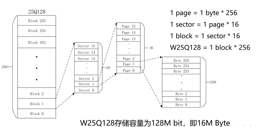
W25Q128将16M的容量分为256个块(Block),每个块大小为64K字节,每个块又分为16个扇区(Sector),每个扇区4K个字节。W25Q128的最小擦除单位为一个扇区,也就是每次必须擦除4K个字节。芯片ID如下所示。
0XEF13,表示芯片型号为W25Q800XEF14,表示芯片型号为W25Q160XEF15,表示芯片型号为W25Q320XEF16,表示芯片型号为W25Q640XEF17,表示芯片型号为W25Q128
16.演示效果
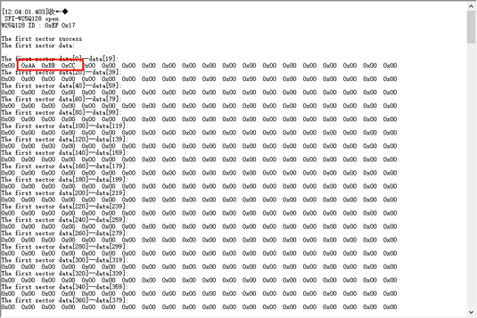
开机会打印W25Q128的ID,ID为0XEF17,实际如下所示。
并且之前保存的数据也正确读取出来了。
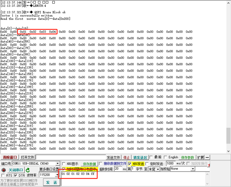
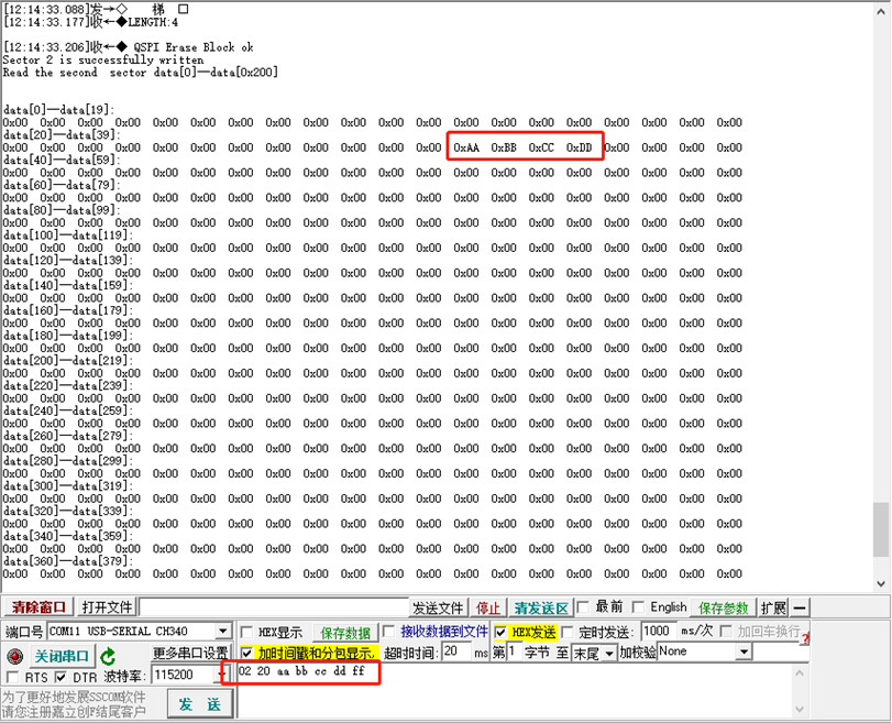
定义数组DataBuff,其中DataBuff[0]表示写入扇区, DataBuff[1]表示写入位置,剩下的为写入数据,同时以0xff结尾。
分别输入数据 01 02 01 02 03 04 ff与02 20 aa bb cc dd ff
17.主程序代码
#include "hal_data.h"
#include
#include "W25Qx.h"
FSP_CPP_HEADER
void R_BSP_WarmStart(bsp_warm_start_event_t event);
FSP_CPP_FOOTER

void uart1_data(void);

#define BUFFERSIZE 255           //可以接收的最大字符个数
uint8_t ReceiveBuff[BUFFERSIZE]; //接收缓冲区
uint8_t recv_end_flag = 0,Rx_len=0;//接收完成中断标志,接收到字符长度

uint8_t wData1[0x200];
uint8_t wData2[0x200];
uint8_t wData3[0x200];

uint8_t rData1[0x200];
uint8_t rData2[0x200];
uint8_t rData3[0x200];
uint8_t ID[4];
uint32_t i;

uint8_t flag[1] ;
int i_flag = 0;


fsp_err_t err = FSP_SUCCESS;
volatile bool uart_send_complete_flag = false;
uint8_t RxBuff[1];      //进入中断接收数据的数组
uint8_t DataBuff[5000]; //保存接收到的数据的数组
int RxLine=0;           //接收到的数据长度
int Rx_flag=0;                  //接受到数据标志
int Rx_flag_finish=0;                  //接受完成或者时间溢出
void user_uart_callback (uart_callback_args_t * p_args)
{
    if(p_args->event == UART_EVENT_TX_COMPLETE)
    {
        uart_send_complete_flag = true;
    }

    if(p_args->event ==     UART_EVENT_RX_CHAR)
    {
        RxBuff[0] = p_args->data;
        RxLine++;                      //每接收到一个数据,进入回调数据长度加1
        DataBuff[RxLine-1]=RxBuff[0];  //把每次接收到的数据保存到缓存数组
        Rx_flag=1;
        Rx_len++;
        if(RxBuff[0]==0xff)            //接收结束标志位,这个数据可以自定义,根据实际需求,这里只做示例使用,不一定是0xff
        {
            Rx_flag_finish=1;
            Rx_len--;
        }
        RxBuff[0]=0;
    }
}

#ifdef __GNUC__                                 //串口重定向
    #define PUTCHAR_PROTOTYPE int __io_putchar(int ch)
#else
    #define PUTCHAR_PROTOTYPE int fputc(int ch, FILE *f)
#endif

PUTCHAR_PROTOTYPE
{
        err = R_SCI_UART_Write(&g_uart1_ctrl, (uint8_t *)&ch, 1);
        if(FSP_SUCCESS != err) __BKPT();
        while(uart_send_complete_flag == false){}
        uart_send_complete_flag = false;
        return ch;
}

int _write(int fd,char *pBuffer,int size)
{
    for(int i=0;ievent)
    {
        g_transfer_complete = true;
    }
}
/*******************************************************************************************************************//**
 * main() is generated by the RA Configuration editor and is used to generate threads if an RTOS is used.  This function
 * is called by main() when no RTOS is used.
 **********************************************************************************************************************/
void hal_entry(void)
{
    /* TODO: add your own code here */

    err = R_SCI_UART_Open(&g_uart1_ctrl, &g_uart1_cfg);
    assert(FSP_SUCCESS == err);
    err = R_SPI_Open(&g_spi0_ctrl, &g_spi0_cfg);
    assert(FSP_SUCCESS == err);
    printf("\r\n SPI-W25Q128 open\n");
    /*##-1- Read the device ID  ########################*/
    BSP_W25Qx_Init();//初始化W25Q128
    BSP_W25Qx_Read_ID(ID);//读取ID
    if((ID[0] != 0xEF) | (ID[1] != 0x17))
    {
        printf("SPI-W25Q128 error");
    }
    else//ID正确,打印ID
    {
        printf("W25Q128 ID : ");
        for(i=0;i<2;i++)
        {
            printf("0x%02X ",ID[i]);
        }
        printf("\r\n\r\n");
    }

    /**************************读取第1扇区数据**************************************************************/
     /*##-3- Read the flash     ########################*/
    /*读取数据,rData读取数据的指针,起始地址0x00,读取数据长度0x200*/
    if(BSP_W25Qx_Read(rData1,0x0,0x200)== W25Qx_OK)
        printf("The first sector success\n");
    else
        printf("The first sector error\n");
    /*打印数据*/
    printf("The first sector data: \r\n");
    for(i =0;i<0x200;i++)
    {
        if(i%20==0)
            printf("\nThe first sector data[%d]--data[%d]: \r\n",i,i+19);
        printf("0x%02X  ",rData1[i]);
    }
        printf("\n");
    /**************************读取第2扇区数据**************************************************************/
    /*##-3- Read the flash     ########################*/
    /*读取数据,rData读取数据的指针,起始地址0x1000,读取数据长度0x200*/
     if(BSP_W25Qx_Read(rData2,0x1000,0x200)== W25Qx_OK)
         printf("The second sector success\n");
     else
         printf("The second sector error\n");
     /*打印数据*/
    printf("The second sector data: \r\n");

    for(i =0;i<0x200;i++)
    {
        if(i%20==0)
            printf("\nThe second sector data[%d]--data[%d]: \r\n",i,i+19);
        printf("0x%02X  ",rData2[i]);
        }
    printf("\n");
    /**************************读取第3扇区数据**************************************************************/
    /*##-3- Read the flash     ########################*/
    /*读取数据,rData读取数据的指针,起始地址0x2000,读取数据长度0x200*/
    if(BSP_W25Qx_Read(rData3,0x2000,0x200)== W25Qx_OK)
        printf("The third  sector success\n");
    else
        printf("The third  sector error\n");
    /*打印数据*/
     printf("The third  sector data: \r\n");
     for(i =0;i<0x200;i++)
    {
         if(i%20==0)
             printf("\nThe third  sector data[%d]--data[%d]: \r\n",i,i+19);
         printf("0x%02X  ",rData3[i]);
    }
    printf("\n");
    /**************************清除第1扇区数据为0**************************************************************/
    /*##-1- Erase Block ##################################*/
    if(BSP_W25Qx_Erase_Block(0) == W25Qx_OK)
        printf(" QSPI Erase Block ok\r\n");
    else
        printf("error\r\n");
    /*##-1- Written to the flash ########################*/
     /* fill buffer */
     printf(" Clear the first sector data[0]--data[0x200]\r\n");
     for(i =0;i<0x200;i ++)
     {
         wData1[i] = 0;
         rData1[i] = 0;
     }
     /*写入数据,wData写入数据的指针,起始地址0x00,写入数据长度0x200*/
     if(BSP_W25Qx_Write(wData1,0x00,0x200)== W25Qx_OK)
         printf("Clear success\r\n");
     else
         printf("Clear error\r\n");

     /*##-1- Read the flash     ########################*/
     /*读取数据,rData读取数据的指针,起始地址0x00,读取数据长度0x200*/
     if(BSP_W25Qx_Read(rData1,0x00,0x200)== W25Qx_OK)
         printf("Read the first sector data[0]--data[0x200]\r\n\r\n");
     else
         printf("Read error\r\n\r\n");
     /*打印数据*/
     printf("the first sector data[0]--data[0x200]: \r\n");
     for(i =0;i<0x200;i++)
     {
         if(i%20==0)
             printf("\ndata[%d]--data[%d]:\r\n",i,i+19);
         printf("0x%02X  ",rData1[i]);
     }
     printf("\n");
    /**************************清除第2扇区数据为0**************************************************************/
    /*##-2- Erase Block ##################################*/
    if(BSP_W25Qx_Erase_Block(0x1000) == W25Qx_OK)
        printf(" QSPI Erase Block ok\r\n");
    else
        printf("error\r\n");
    /*##-2- Written to the flash ########################*/
    /* fill buffer */
    printf(" Clear the second sector data[0]--data[0x200]\r\n");
    for(i =0;i<0x200;i ++)
    {
        wData2[i] = 0;
        rData2[i] = 0;
    }
    /*写入数据,wData写入数据的指针,起始地址0x1000,写入数据长度0x200*/
    if(BSP_W25Qx_Write(wData2,0x1000,0x200)== W25Qx_OK)
        printf("Clear success\r\n");
    else
        printf("Clear error\r\n");
    /*##-2- Read the flash     ########################*/
    /*读取数据,rData读取数据的指针,起始地址0x00,读取数据长度0x200*/
    if(BSP_W25Qx_Read(rData2,0x1000,0x200)== W25Qx_OK)
        printf("Read the second sector data[0]--data[0x200]\r\n\r\n");
    else
        printf("Read error\r\n\r\n");
    /*打印数据*/
    printf("the first sector data[0]--data[0x200]: \r\n");
    for(i =0;i<0x200;i++)
    {
        if(i%20==0)
            printf("\ndata[%d]--data[%d]:\r\n",i,i+19);
        printf("0x%02X  ",rData2[i]);
        }
    printf("\n");
    /**************************清除第3扇区数据为0**************************************************************/
    /*##-3- Erase Block ##################################*/
    if(BSP_W25Qx_Erase_Block(0x2000) == W25Qx_OK)
        printf(" QSPI Erase Block ok\r\n");
    else
        printf("error\r\n");
    /*##-3- Written to the flash ########################*/
    /* fill buffer */
    printf(" Clear the third sector data[0]--data[0x200]\r\n");
    for(i =0;i<0x200;i ++)
    {
        wData3[i] = 0;
        rData3[i] = 0;
    }
    /*写入数据,wData写入数据的指针,起始地址0x2000,写入数据长度0x200*/
    if(BSP_W25Qx_Write(wData3,0x2000,0x200)== W25Qx_OK)
        printf("Clear success\r\n");
    else
        printf("Clear error\r\n");
    /*##-3- Read the flash     ########################*/
    /*读取数据,rData读取数据的指针,起始地址0x00,读取数据长度0x200*/
    if(BSP_W25Qx_Read(rData3,0x2000,0x200)== W25Qx_OK)
        printf("Read the third sector data[0]--data[0x200]\r\n\r\n");
    else
        printf("Read error\r\n\r\n");
    /*打印数据*/
    printf("the first third data[0]--data[0x200]: \r\n");
    for(i =0;i<0x200;i++)
    {
        if(i%20==0)
            printf("\ndata[%d]--data[%d]:\r\n",i,i+19);
        printf("0x%02X  ",rData3[i]);
    }
                printf("\n");
    while(1)
    {
        uart1_data();
        R_BSP_SoftwareDelay(100, BSP_DELAY_UNITS_MILLISECONDS); // NOLINT100->160
    }
#if BSP_TZ_SECURE_BUILD
    /* Enter non-secure code */
    R_BSP_NonSecureEnter();
#endif
}


void uart1_data(void)
{
    if(Rx_flag_finish ==1)//接收完成标志
    {
        if(DataBuff[0]==0x01)
        {
            printf("LENGTH:%d\n",Rx_len-2);
            for(int i =0;i;i++)>;i++)>
声明:本文内容及配图由入驻作者撰写或者入驻合作网站授权转载。文章观点仅代表作者本人,不代表电子发烧友网立场。文章及其配图仅供工程师学习之用,如有内容侵权或者其他违规问题,请联系本站处理。
举报投诉
-
mcu
+关注
关注
146文章
17414浏览量
353539 -
ARM
+关注
关注
134文章
9200浏览量
370438 -
嵌入式
+关注
关注
5098文章
19242浏览量
309092 -
开发板
+关注
关注
25文章
5187浏览量
98716
发布评论请先 登录
相关推荐
【瑞萨RA2L1入门学习】1. 点亮LED
首次使用瑞萨单片机,先说一下使用感受。
本次学习使用的是RA-Eco-RA2L1-48PIN-V1.0开发板+e2studio(官方的集成开发环境)+RAFP(官方的程序烧录工具)。
发表于 01-29 22:17
瑞萨e2studio(1)----瑞萨芯片之搭建FSP环境
视频教学
样品申请
请勿添加外链
e2studio软件
e2studio是瑞萨的集成开发环境,FSP 提供了众多可提高效率的工具,用于开发针对瑞
发表于 09-30 15:28
STM32CUBEMX(13)--SPI,W25Q128外部Flash移植
上节省空间,提供方便,正是出于这种简单易用的特性,越来越多的芯片集成了这种通信协议,比如 EEPROM,FLASH,实时时钟,AD转换器。 W25Q128 是一款SPI接口的Flash
发表于 09-30 14:41
物联网行业中Nor Flash的软件设计分享_W25Q128的软件设计方案
一 概述 W25Q128是一种NOR Flash芯片,掉电后数据不丢失的特点。 W25Q128FV阵列被组织成65,536个可编程页面,每个页面256字节。每次最多可编程256字节。可
瑞萨e2studio----SPI速率解析
在嵌入式系统的设计中,串行外设接口(SPI)的通信速率是一个关键参数,它直接影响到系统的性能和稳定性。瑞萨电子的RA4M2微控制器为开发者提供了灵活而强大的

ESP32外部flash与spi外设冲突怎么解决?
硬件: ESP32 ,W25Q128 SPI显示器
库:IDF4.0.1
使用hspi挂载了外部16MB的W25Q128,并同时挂载了SPI
发表于 06-25 06:19
ESP32-S3-WROOM-1-N16R8在外部FLASH中挂载FATFS出现错误的原因?
,
.quadwp_io_num = -1,
外部FLSAH型号为W25Q128,使用标准SPI通讯。
接线方式为
CSGPIO10
DO GPIO13
CLK GPIO12
DI GPIO11
但运行之后出现错误,错误
发表于 06-05 07:20
【GD32H757Z海棠派开发板使用手册】第十一讲 SPI-SPI NOR FLASH读写实验
通过本实验主要学习以下内容:
•SPI简介
•GD32H7 SPI简介
•SPI NOR FLASH——GD
具有双/四SPI和QPI的串行闪存W25Q128FV数据手册
电子发烧友网站提供《具有双/四SPI和QPI的串行闪存W25Q128FV数据手册.pdf》资料免费下载
发表于 04-25 17:11
•0次下载
如何使用SPI的DMA模式读写FLASH?
环境:HAL库 + USB + W25Q64 + Fatfs
硬件:stm32f103c8t6 + MX25L64
我使用普通模式,完成在W25Q64中写入文件,通过USB可以再PC中
发表于 04-16 07:59
STM32F103ZET6将SPI+W25QXX的程序移植后,步进电机均转速转慢的原因?
SPI2+W25Q16
多个步进电机脉冲均由多个不同定时器PWM(TIM1TIM2TIM4TIM8)或定时器中断(TIM1)生成;
现象:
1、原程序运行正常,步进电机均正常,通过示波器测量,步进脉冲信号正常
发表于 04-02 08:30
瑞萨电子推出采用自研RISC-V CPU内核的通用32位MCU
5.5V
封装:16 WLCSP、24/32/48 QFN封装(QFP可选)
R9A02G021 RISC-V MCU得到瑞萨e² studio集成开发环境(IDE)的全方位支持,客户
发表于 03-30 22:08
NUCLEO-H7A3ZIQ使用keil外部下载算法后提示Flash Timeout的原因?
我用ospi驱动w25q128,可以读出id,可以写入和读取数据。然后自己写了个KEIL的外部下载算法,修改了链接器脚本让图片资源存储在w25q12
发表于 03-19 06:18


 工商网监
工商网监
评论