 瑞萨e2studio----基于DTC的多通道ADC采集

1.概述
本篇文章主要介绍如何使用e2studio对瑞萨进行DTC配置,并且对多通道ADC进行采集。
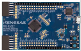
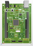
2.硬件准备
首先需要准备一个开发板,这里我准备的是芯片型号 R7FA2L1AB2DFL 的开发板。
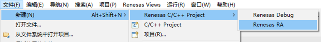
3.新建工程
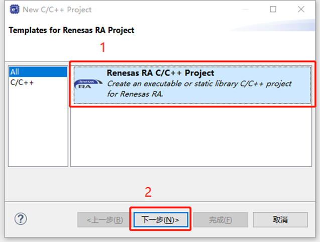
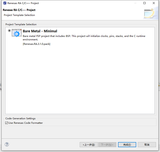
4.工程模板
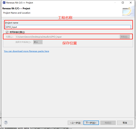
5.保存工程路径
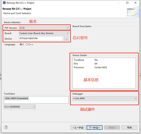
6.芯片配置
本文中使用R7FA2L1AB2DFL来进行演示。
7
7.工程模板选择
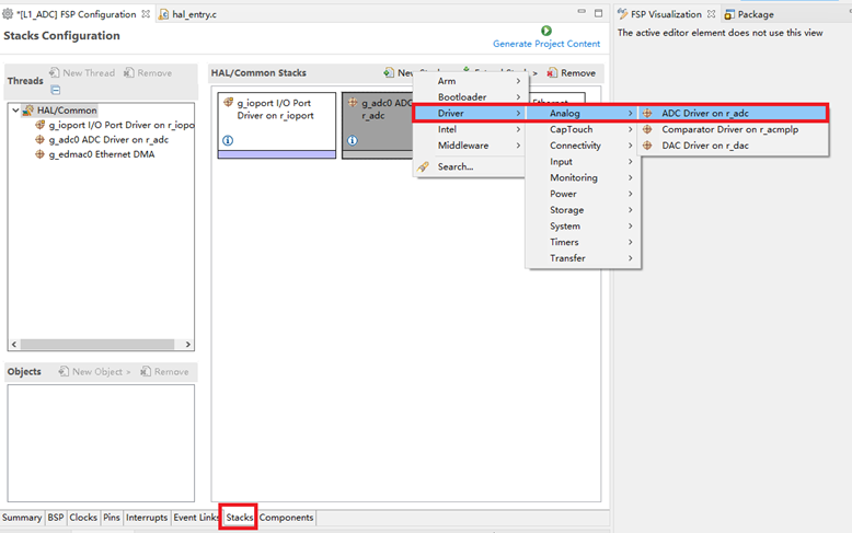
8.ADC配置
点击Stacks->New Stack->Driver->Analog -> ADC Driver on r_adc。
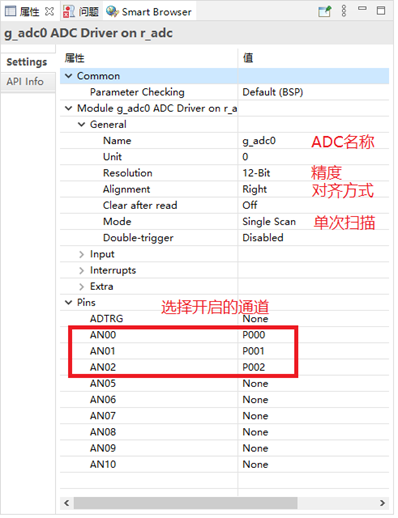
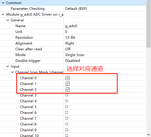
9.ADC属性配置
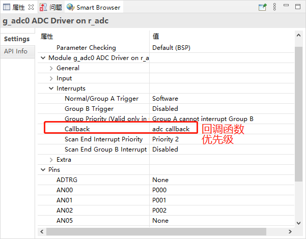
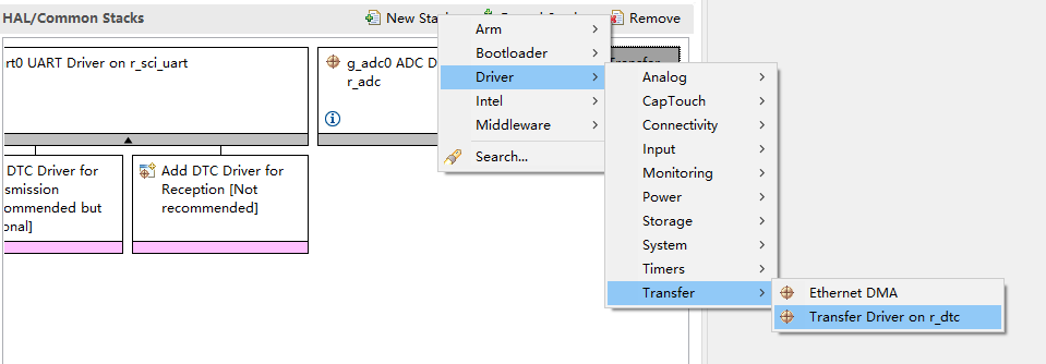
10.DTC配置
点击Stacks->New Stack->Driver->Transfer-> Transfer Driver on r_dtc。
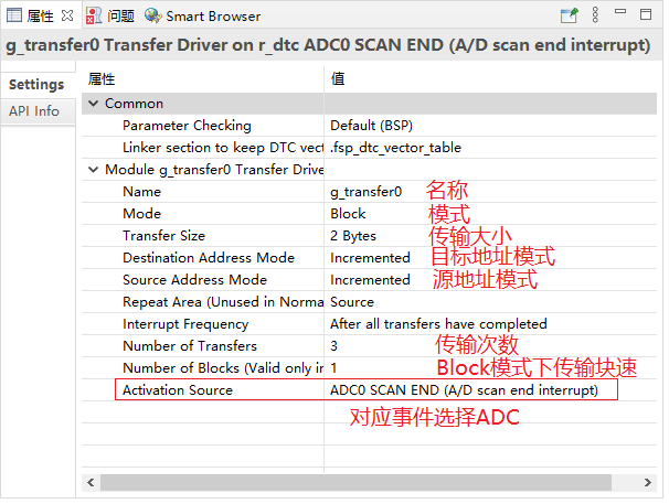
11.DTC属性配置
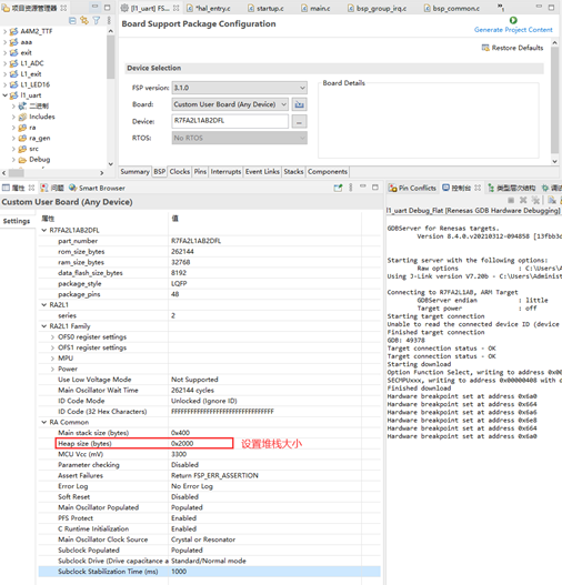
12.设置e2studio堆栈
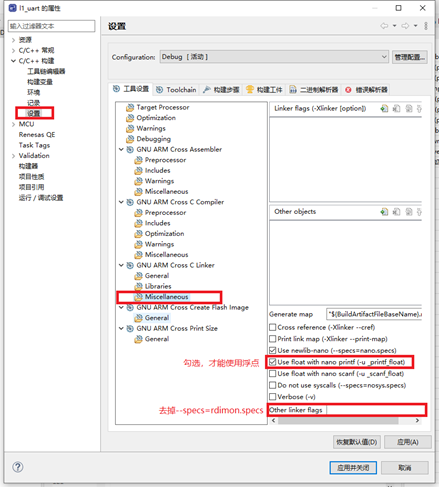
13.e2studio的重定向printf设置
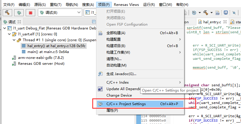
C++ 构建->设置->GNU ARM Cross C Linker->Miscellaneous去掉Other linker flags中的 “--specs=rdimon.specs”
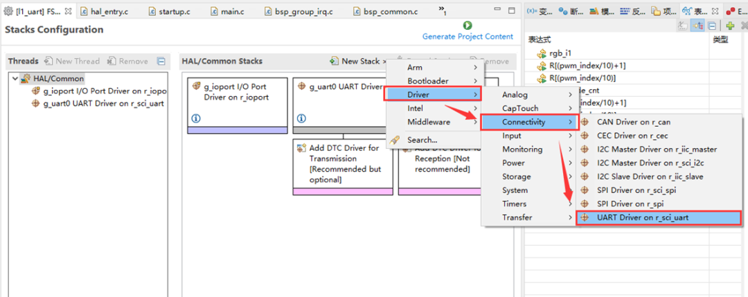
14.UART配置
点击Stacks->New Stack->Driver->Connectivity -> UART Driver on r_sci_uart。
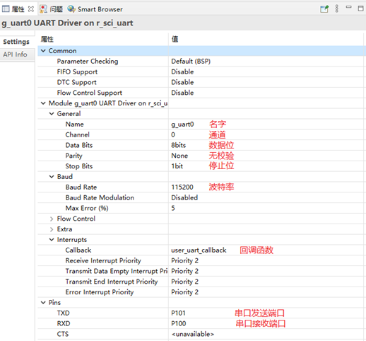
15.UART属性配置
配置串口,用于打印数据。
16.printf输出重定向到串口
打印最常用的方法是printf,所以要解决的问题是将printf的输出重定向到串口,然后通过串口将数据发送出去。
注意一定要加上头文件#include
#ifdef __GNUC__ //串口重定向
#define PUTCHAR_PROTOTYPE int __io_putchar(int ch)
#else
#define PUTCHAR_PROTOTYPE int fputc(int ch, FILE *f)
#endif
PUTCHAR_PROTOTYPE
{
err = R_SCI_UART_Write(&g_uart0_ctrl, (uint8_t *)&ch, 1);
if(FSP_SUCCESS != err) __BKPT();
while(uart_send_complete_flag == false){}
uart_send_complete_flag = false;
return ch;
}
int _write(int fd,char *pBuffer,int size)
{
for(int i=0;i;i++)>17.代码
#include "hal_data.h"
#include
FSP_CPP_HEADER
void R_BSP_WarmStart(bsp_warm_start_event_t event);
FSP_CPP_FOOTER
fsp_err_t err = FSP_SUCCESS;
unsigned char send_buff[100];
volatile bool uart_send_complete_flag = false;
void user_uart_callback (uart_callback_args_t * p_args)
{
if(p_args->event == UART_EVENT_TX_COMPLETE)
{
uart_send_complete_flag = true;
}
}
#ifdef __GNUC__ //串口重定向
#define PUTCHAR_PROTOTYPE int __io_putchar(int ch)
#else
#define PUTCHAR_PROTOTYPE int fputc(int ch, FILE *f)
#endif
PUTCHAR_PROTOTYPE
{
err = R_SCI_UART_Write(&g_uart0_ctrl, (uint8_t *)&ch, 1);
if(FSP_SUCCESS != err) __BKPT();
while(uart_send_complete_flag == false){}
uart_send_complete_flag = false;
return ch;
}
int _write(int fd,char *pBuffer,int size)
{
for(int i=0;ievent == ADC_EVENT_SCAN_COMPLETE )
{
err = R_DTC_Reset( &g_transfer0_ctrl,
(void*)&R_ADC0->ADDR[0], // reset source address
&adc_result_buffer[0], // reset destination address
1 ); // reset block size
if( FSP_SUCCESS != err )
{
__BKPT(1);
}
}
}
void hal_entry(void)
{
/* TODO: add your own code here */
err = R_SCI_UART_Open(&g_uart0_ctrl, &g_uart0_cfg);
assert(FSP_SUCCESS == err);
adc_status_t adc_status;
err = R_ADC_Open(&g_adc0_ctrl, &g_adc0_cfg);
assert(FSP_SUCCESS == err);
err = R_ADC_StatusGet (&g_adc0_ctrl, &adc_status);
assert(FSP_SUCCESS == err);
err = R_ADC_ScanCfg(&g_adc0_ctrl, &g_adc0_channel_cfg);
assert(FSP_SUCCESS == err);
// Source is first ADC result register
g_transfer0_cfg.p_info->p_src = (void*)&R_ADC0->ADDR[0];
// Destination is results buffer
g_transfer0_cfg.p_info->p_dest = &adc_result_buffer[0];
/* Open the transfer instance with initial configuration. */
err = R_DTC_Open(&g_transfer0_ctrl, &g_transfer0_cfg);
/* Handle any errors. This function should be defined by the user. */
assert(FSP_SUCCESS == err);
/* Enable the DTC to handle incoming transfer requests. */
err = R_DTC_Enable(&g_transfer0_ctrl);
assert(FSP_SUCCESS == err);
while(1)
{
/* In software trigger mode, start a scan by calling R_ADC_ScanStart(). In other modes, enable external
* triggers by calling R_ADC_ScanStart(). */
err = R_ADC_ScanStart(&g_adc0_ctrl);
assert(FSP_SUCCESS == err);
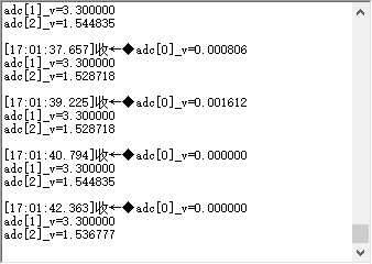
printf("adc[0]_v=%f\n",(float)adc_result_buffer[0]/4095*3.3);
printf("adc[1]_v=%f\n",(float)adc_result_buffer[1]/4095*3.3);
printf("adc[2]_v=%f\n",(float)adc_result_buffer[2]/4095*3.3);
R_BSP_SoftwareDelay(1000, BSP_DELAY_UNITS_MILLISECONDS); // NOLINT100->160
}
#if BSP_TZ_SECURE_BUILD
/* Enter non-secure code */
R_BSP_NonSecureEnter();
#endif
};i++)>18.多通道ADC采集通过DTC传输例程
现在设置3个ADC通道的输入电压如下所示。
| ADC通道 | 管脚 |
输入电压 |
| AN0 |
P000 |
GND(0V) |
| AN1 | P001 | VCC(3.3V) |
| AN2 | P002 | 1.5V |
19.演示效果
通过串口打印出的数据如下所示。
原创:By RA_Billy Xiao
原文标题:瑞萨e2studio----基于DTC的多通道ADC采集
文章出处:【微信公众号:RA生态工作室】欢迎添加关注!文章转载请注明出处。
声明:本文内容及配图由入驻作者撰写或者入驻合作网站授权转载。文章观点仅代表作者本人,不代表电子发烧友网立场。文章及其配图仅供工程师学习之用,如有内容侵权或者其他违规问题,请联系本站处理。
举报投诉
-
mcu
+关注
关注
146文章
17400浏览量
353250 -
ARM
+关注
关注
134文章
9193浏览量
370169 -
嵌入式
+关注
关注
5097文章
19228浏览量
308788 -
开发板
+关注
关注
25文章
5167浏览量
98591
发布评论请先 登录
相关推荐
基于瑞萨RA0E1开发板的IIC OLED测试
基于前面关于瑞萨e² studio开发软件的使用,以及工程测试基础,本文进一步探索实现硬件IIC OLED的文字和图片显示。
【瑞萨RA2L1入门学习】2. PWM呼吸灯
.烧录程序:
3.实验图片:
经过这两天的使用,发现e2studio中的stacks页面还是挺好用的,可以拖拽函数,编写程序更加方便快捷。在stacks页面还能看到用到了哪些堆栈,非常的赞。
本人第一次使用该开发板,作为入门学习,主要是体验一下瑞
发表于 01-30 21:55
【瑞萨RA2L1入门学习】1. 点亮LED
首次使用瑞萨单片机,先说一下使用感受。
本次学习使用的是RA-Eco-RA2L1-48PIN-V1.0开发板+e2studio(官方的集成开发环境)+RAFP(官方的程序烧录工具)。
发表于 01-29 22:17
【瑞萨RA2L1入门学习】+ MacOS安装e2studio
在win11下面可以有很多开发方式,但是在macOS下面选择开发方式就是安装e2studio for mac是比较好的方法。
1、下载安装包:
https://www.renesas.cn/zh
发表于 01-22 19:00
瑞萨e2 studio中Reality AI组件的使用方法
本实验将为您介绍如何在e2 studio中使用Reality AI相关组件来进行AI开发,主要涉及如何使用Reality AI Data shipper/collector,Reality AI

瑞萨e2studio(1)----瑞萨芯片之搭建FSP环境
视频教学
样品申请
请勿添加外链
e2studio软件
e2studio是瑞萨的集成开发环境,FSP 提供了众多可提高效率的工具,用于开发针对瑞
发表于 09-30 15:28
试用活动 | 100套!!瑞萨RA6E2/RA4E2开发板评测活动
活动简介:
瑞萨RA6E2/RA4E2开发板评测活动是一个针对瑞萨电子推出的通用微控制器(MCU

瑞萨e2studio----SPI速率解析
在嵌入式系统的设计中,串行外设接口(SPI)的通信速率是一个关键参数,它直接影响到系统的性能和稳定性。瑞萨电子的RA4M2微控制器为开发者提供了灵活而强大的SPI配置选项,确保可以根据不同的应用场
瑞萨电子推出采用自研RISC-V CPU内核的通用32位MCU
5.5V
封装:16 WLCSP、24/32/48 QFN封装(QFP可选)
R9A02G021 RISC-V MCU得到瑞萨e² studio集成开发环境(IDE)的全方位支持,客户
发表于 03-30 22:08


 工商网监
工商网监
评论