 i.MX RT600 BCLK受干扰影响WS频率解决方案
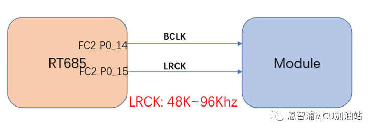
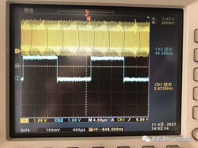
48Khz 采样率,32bit, 2通道, BCLK输出3.072Mhz。
测试发现现象很奇怪,如果BCLK连接的模块阻抗改变,会导致正常应该输出48K的LRCK(WS)频率会变动,有时候变成96Khz,客户的模块是专用的ASIC。
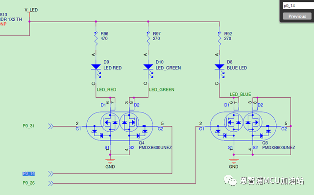
客户反应,这个问题同样可以在NXP MIMXRT685-AUD-EVK板子上复现,因为AUD-EVK FC2P0_14连接到了外部LED的驱动电路:
如果是官方的代码配置,不会复现问题,如果是使用客户的代码,能够复现问题。
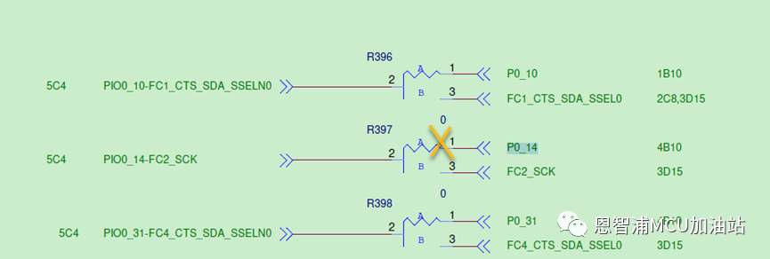
如果断开R397 1_2的电阻,问题就不会复现,连接之后就会复现。
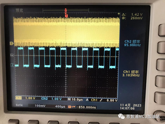
所谓复现:测试P0_15 LRCK采样率从期望的48Khz变成了96Khz:
所谓不复现:测试P0_15 LRCK采样率就是期望的48Khz:
从I2S的构架上讲,不应该出现具体I2S IP的配置因为外部的驱动情况导致不同的输出频率,而且官方的代码直接修改接口和引脚也不会出现,那么问题究竟出在哪里呢?
问题分析与解决方案经过查看官方SDK的配置和客户提供的代码,发现差别很简单,在于pinmux.c对于P0_14, P0_15的配置,客户复现问题的配置如下:
const uint32_t port0_pin14_config = (/* Pin is configured as FC2_SCK */
IOPCTL_PIO_FUNC1 |
/* Disable pull-up / pull-down function */
IOPCTL_PIO_PUPD_DI |
/* Enable pull-down function */
IOPCTL_PIO_PULLDOWN_EN |
/* Enables input buffer function */
IOPCTL_PIO_INBUF_EN |
/* Normal mode */
IOPCTL_PIO_SLEW_RATE_NORMAL |
/* Normal drive */
IOPCTL_PIO_FULLDRIVE_DI |
/* Analog mux is disabled */
IOPCTL_PIO_ANAMUX_DI |
/* Pseudo Output Drain is disabled */
IOPCTL_PIO_PSEDRAIN_DI |
/* Input function is not inverted */
IOPCTL_PIO_INV_DI);
/* PORT0 PIN14 (coords: A3) is configured as FC2_SCK */
IOPCTL_PinMuxSet(IOPCTL, 0U, 14U, port0_pin14_config);
const uint32_t port0_pin15_config = (/* Pin is configured as FC2_TXD_SCL_MISO_WS */
IOPCTL_PIO_FUNC1 |
/* Disable pull-up / pull-down function */
IOPCTL_PIO_PUPD_DI |
/* Enable pull-down function */
IOPCTL_PIO_PULLDOWN_EN |
/* Enables input buffer function */
IOPCTL_PIO_INBUF_EN |
/* Normal mode */
IOPCTL_PIO_SLEW_RATE_NORMAL |
/* Normal drive */
IOPCTL_PIO_FULLDRIVE_DI |
/* Analog mux is disabled */
IOPCTL_PIO_ANAMUX_DI |
/* Pseudo Output Drain is disabled */
IOPCTL_PIO_PSEDRAIN_DI |
/* Input function is not inverted */
IOPCTL_PIO_INV_DI);
/* PORT0 PIN15 (coords: A5) is configured as FC2_TXD_SCL_MISO_WS */
IOPCTL_PinMuxSet(IOPCTL, 0U, 15U, port0_pin15_config);
官方不复现问题的配置如下:
const uint32_t port0_pin14_config = (/* Pin is configured as FC2_SCK */
IOPCTL_PIO_FUNC1 |
/* Disable pull-up / pull-down function */
IOPCTL_PIO_PUPD_DI |
/* Enable pull-down function */
IOPCTL_PIO_PULLDOWN_EN |
/* Enables input buffer function */
IOPCTL_PIO_INBUF_EN |
/* Normal mode */
IOPCTL_PIO_SLEW_RATE_NORMAL |
/* Normal drive */
IOPCTL_PIO_FULLDRIVE_EN |
/* Analog mux is disabled */
IOPCTL_PIO_ANAMUX_DI |
/* Pseudo Output Drain is disabled */
IOPCTL_PIO_PSEDRAIN_DI |
/* Input function is not inverted */
IOPCTL_PIO_INV_DI);
/* PORT0 PIN14 (coords: A3) is configured as FC2_SCK */
IOPCTL_PinMuxSet(IOPCTL, 0U, 14U, port0_pin14_config);
const uint32_t port0_pin15_config = (/* Pin is configured as FC2_TXD_SCL_MISO_WS */
IOPCTL_PIO_FUNC1 |
/* Disable pull-up / pull-down function */
IOPCTL_PIO_PUPD_DI |
/* Enable pull-down function */
IOPCTL_PIO_PULLDOWN_EN |
/* Enables input buffer function */
IOPCTL_PIO_INBUF_EN |
/* Normal mode */
IOPCTL_PIO_SLEW_RATE_NORMAL |
/* Normal drive */
IOPCTL_PIO_FULLDRIVE_EN |
/* Analog mux is disabled */
IOPCTL_PIO_ANAMUX_DI |
/* Pseudo Output Drain is disabled */
IOPCTL_PIO_PSEDRAIN_DI |
/* Input function is not inverted */
IOPCTL_PIO_INV_DI);
/* PORT0 PIN15 (coords: A5) is configured as FC2_TXD_SCL_MISO_WS */
IOPCTL_PinMuxSet(IOPCTL, 0U, 15U, port0_pin15_config);
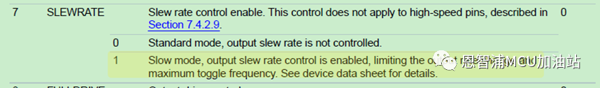
实际上,只要BCLK P0_14的引脚配置为FULL drive即可。

可以看到,如果配置为Full output driver,驱动能力是normal输出的两倍。所以,问题出在BCLK的引脚驱动能力这块。
然而,推荐客户改变驱动能力的方式,纵然可以输出正确的48Khz采样率波形,客户并不接受,认为高驱动能力也代表着功耗的加大,而他们的产品是对功耗要求极高的,必须要在普通驱动能力下解决问题。所以进一步分析波形,通过使用高采样率的示波器20Gsa/s,2G探头抓取出问题时候的BCLK,可以发现有一些毛刺:
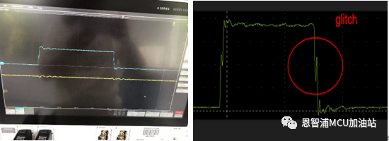
通过内部的沟通,也认为这个BCLK毛刺是导致问题的原因。这里需要注意的是,有些示波器,如果采样率低可能抓不到这个毛刺,还有些探头,阻抗比较小,导致探头加上到BCLK,直接问题消失的情况,所以建议使用高阻抗探头,比如1M欧,1G采样率以上的探头即可抓到。
由于客户不接受驱动能力的改变,所以这里还可以考虑改变斜率,让上升下降变缓,滤掉毛刺区域,改变配置如下:
const uint32_t port0_pin14_config = (/* Pin is configured as FC2_SCK */
IOPCTL_PIO_FUNC1 |
/* Disable pull-up / pull-down function */
IOPCTL_PIO_PUPD_DI |
/* Enable pull-down function */
IOPCTL_PIO_PULLDOWN_EN |
/* Enables input buffer function */
IOPCTL_PIO_INBUF_EN |
/* Normal mode */
IOPCTL_PIO_SLEW_RATE_SLEW|//0X80|// IOPCTL_PIO_SLEW_RATE_NORMAL |
/* Normal drive */
IOPCTL_PIO_FULLDRIVE_DI |
/* Analog mux is disabled */
IOPCTL_PIO_ANAMUX_DI |
/* Pseudo Output Drain is disabled */
IOPCTL_PIO_PSEDRAIN_DI |
/* Input function is not inverted */
IOPCTL_PIO_INV_DI);
/* PORT0 PIN14 (coords: A3) is configured as FC2_SCK */
IOPCTL_PinMuxSet(IOPCTL, 0U, 14U, port0_pin14_config);
const uint32_t port0_pin15_config = (/* Pin is configured as FC2_TXD_SCL_MISO_WS */
IOPCTL_PIO_FUNC1 |
/* Disable pull-up / pull-down function */
IOPCTL_PIO_PUPD_DI |
/* Enable pull-down function */
IOPCTL_PIO_PULLDOWN_EN |
/* Enables input buffer function */
IOPCTL_PIO_INBUF_EN |
/* Normal mode */
IOPCTL_PIO_SLEW_RATE_NORMAL |
/* Normal drive */
IOPCTL_PIO_FULLDRIVE_DI |
/* Analog mux is disabled */
IOPCTL_PIO_ANAMUX_DI |
/* Pseudo Output Drain is disabled */
IOPCTL_PIO_PSEDRAIN_DI |
/* Input function is not inverted */
IOPCTL_PIO_INV_DI);
/* PORT0 PIN15 (coords: A5) is configured as FC2_TXD_SCL_MISO_WS */
IOPCTL_PinMuxSet(IOPCTL, 0U, 15U, port0_pin15_config);
 测试结果如下:
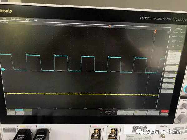
可以看到波形很光滑,毛刺消失,输出也是稳定的48Khz,满足客户不改变驱动能力的要求。
小结
在使用i.MX RT600 FC2做I2S的时候,为了BCLK不受外部电路影响,从而影响到WS的波形频率,建议引脚配置以下二选一:
1.使用Full output drive,提高驱动能力2.使用慢slewrate,滤掉BCLK上升下降小毛刺
最后,特别感谢NXP 苏州SE团队 James Fan 在该解决方案上提供的大力支持!作者:周晶晶
-
mcu
+关注
关注
146文章
17397浏览量
353194 -
恩智浦
+关注
关注
14文章
5898浏览量
108560 -
WS
+关注
关注
0文章
3浏览量
9965 -
i.MX
+关注
关注
1文章
49浏览量
35737 -
I2S
+关注
关注
1文章
66浏览量
42162
原文标题:i.MX RT600 BCLK受干扰影响WS频率解决方案
文章出处:【微信号:NXP_SMART_HARDWARE,微信公众号:恩智浦MCU加油站】欢迎添加关注!文章转载请注明出处。
发布评论请先 登录
相关推荐
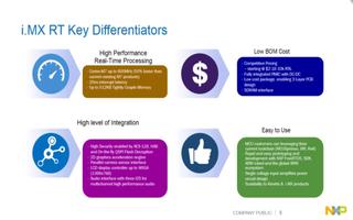
NXP专为边缘AI打造的i.MX RT700跨界MCU到底强在哪?
NXP推出基于i.MX RT106F本地人脸识别解决方案
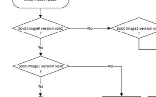
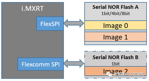
i.MX RT500/600应用案例 串行NOR Flash双程序可交替启动设计
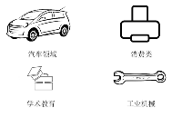
01:i.MX RT的市场应用和参考解决方案
恩智浦i.MX RT600跨界微控制器在功耗、性能和存储器方面有显著特点
i.MX RT开发笔记-08 | i.MX RT1062嵌套中断向量控制器NVIC(按键中断检测)

RT-Thread & NXP 发布 i.MX RT 系列 BSP 新框架
基于i.MX RT单芯片实现的GUI图形显示和语音控制解决方案
适用于i.MX RT500和i.MX RT600 MCU的Xtensa音频框架介绍
基于 NXP i.MX RT1050 的 3D 打印机方案
i.MX RT500/600系列上串行NOR Flash双程序可交替启动设计


 工商网监
工商网监
评论