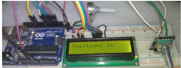
在本教程中,您将学习如何将增量旋转编码器与Arduino连接,以读取旋钮的运动。这对于在机器人和其他应用程序中创建用户界面或读取机械位置非常有用。
您需要的器件
Arduino开发板
1x 增量式旋转编码器(像这样)
4个10 kΩ电阻(R1、R2)
2x 0.1uF 电容器 (C1, C2)
面包板
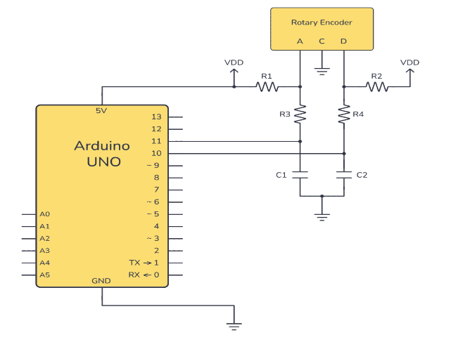
原理图和试验板设置
请注意,在此原理图中,我直接使用旋转编码器,因此它需要一些额外的元件。但您也可以购买旋转编码器板,在板上包含这些额外的组件,以使连接更简单。

原理图中的VDD仅指Arduino的5V电压。
连接此旋转编码器所需的额外组件的连接取自旋转编码器数据表中的建议滤波电路。如果您使用的是不同的编码器,请务必查看数据表中的“建议滤波电路”,因为它可能不同。
它是如何工作的
该电路的工作原理是查看旋转编码器的两个引脚 A 和 B,并检查它们中哪一个先于另一个引脚为高电平。如果 A 先于 B 走高,那就是一个方向。如果 B
先于 A 走高,则方向相反。
连接Arduino旋转编码器电路
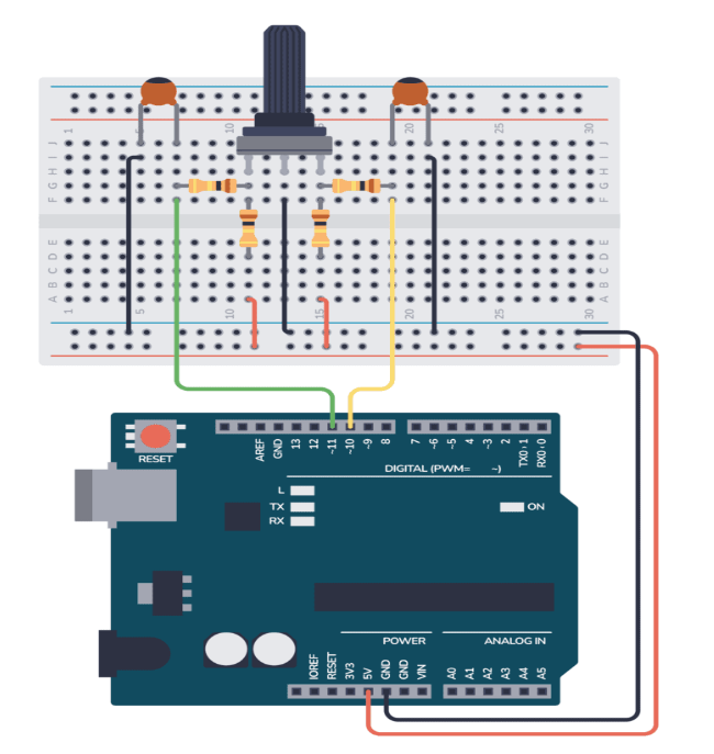
在下图中,您可以看到如何将完整的示例电路连接到面包板上,以及将其连接到Arduino所需的接线。

分步说明
将旋转编码器连接到面包板。
将两个10 kΩ电阻R1和R2从A和B置于5V。
将两个 10 kΩ 电阻 R3 和 R4 分别从 A 和 B 连接到 Arduino 数字引脚 10 和 11。
如图所示放置0.1uF电容(C1和C2),使编码器信号去抖动。
将 C 点接地。
使用 USB 数据线将 Arduino 连接到您的计算机。
将以下代码上传到您的 Arduino。此代码初始化旋转编码器,并在每次转动编码器时使用中断来更新位置计数。
结果将打印到串行端口,以便您可以从串行监视器中读取结果。
// Define the pins used for the encoder
const int encoderPinA = 10;
const int encoderPinB = 11;

// Variables to keep the current and last state
volatile int encoderPosCount = 0;
int lastEncoded = 0;

void setup() {
  Serial.begin(9600);

  // Set encoder pins as input with pull-up resistors
  pinMode(encoderPinA, INPUT_PULLUP);
  pinMode(encoderPinB, INPUT_PULLUP);

  // Attach interrupts to the encoder pins
  attachInterrupt(digitalPinToInterrupt(encoderPinA), updateEncoder, CHANGE);
  attachInterrupt(digitalPinToInterrupt(encoderPinB), updateEncoder, CHANGE);
}

void loop() {
  static int lastReportedPos = -1; // Store the last reported position
  if (encoderPosCount != lastReportedPos) {
    Serial.print("Encoder Position: ");
    Serial.println(encoderPosCount);
    lastReportedPos = encoderPosCount;
  }
}

void updateEncoder() {
  int MSB = digitalRead(encoderPinA); // MSB = most significant bit
  int LSB = digitalRead(encoderPinB); // LSB = least significant bit

  int encoded = (MSB < < 1) | LSB; // Converting the 2 pin value to single number
  int sum  = (lastEncoded < < 2) | encoded; // Adding it to the previous encoded value

  if(sum == 0b1101 || sum == 0b0100 || sum == 0b0010 || sum == 0b1011) encoderPosCount++;
  if(sum == 0b1110 || sum == 0b0111 || sum == 0b0001 || sum == 0b1000) encoderPosCount--;

  lastEncoded = encoded; // Store this value for next time
}
上传此代码后,您可以以 9600 的波特率打开串行监视器,以查看编码器的移动在旋转时的变化。
如果编码器值不稳定或未按预期变化,请根据原理图仔细检查接线,并确保电阻器和电容器正确放置以进行去抖动。
审核编辑:陈陈
-
旋转编码器
+关注
关注
5文章
158浏览量
25953 -
Arduino
+关注
关注
188文章
6468浏览量
186900
发布评论请先 登录
相关推荐
利用Arduino与增量式光电编码器测量速度
增量式旋转编码器设计
Arduino旋转编码器的教程

如何将光学旋转编码器与Arduino连接
基于Sensor API如何添加增量型旋转编码器的驱动
STM32-增量式旋转编码器测量


 如何将增量旋转编码器与Arduino连接


评论