//
//系统设置: Fosc、Fcclk、Fcco、Fpclk
//#define Fosc 12000000
//#define Fcclk (Fosc * 5)
//#define Fcco (Fcclk *4)
//#define Fpclk (Fcclk / 4) * 4
//Fpclk=60000000
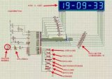
接线说明: 使用 3根 1P杜邦线连接核心板 P04/P06/P07口接底板 JP26
具体接线为:P04-SHCP,P06-DS , P07-STCP。
跳线说明:短接 J70
实验现象:数码管先逐段扫描,然后显示0-9
*************************************************************
#define IN_MAIN
#include "config.h"
#include "LPC2103_lian.H"
#include "ADC.h"
#include "I2C.h"
#include "IAP.h"
#include "Legacy_GPIO.h"
#include "RTC.h"
#include "SPI.h"
#include "SSP.h"
#include "Time.h"
#include "UART.h"
#include "WatchDog.h"
#include "ISR.h"
#pragma import(__use_no_semihosting_swi)
#define rclk_0() IO0CLR=IO0CLR|p07 //74959锁存时钟
#define rclk_1() IO0SET=IO0SET|p07
const uint8 tb[]={
0xfe,0xfd,0xfb,0xf7,0xef,0xdf,0xbf,0x7f,
0xC0,0xF9,0xA4,0xB0,0x99,0x92,0x82,0xF8,0x80,0x90,
0x88,0x83,0xc6,0xa1,0x86,0x8e,0x00,
};
const uint8 smg_text[]={0xfe,0xfd,0xfb,0xf7,0xef,0xdf,0xbf,0x7f,};
const uint8 smg[]={0xC0,0xF9,0xA4,0xB0,0x99,0x92,0x82,0xF8,0x80,0x90,0x00,};
// 0 1 2 3 4 5 6 7 8 9 all
const uint8 smg_bit[]={0x01,0x02,0x04,0x08,0x10,0x20,0x40,0x80,0xff,};
uint8 c;
uint8 d;
void IRQ_Exception(void)
{
}
//**********************函数定义************************
void delay(uint32 dly);
void spiinit(void);
uint8 senddata_mspi(uint8 uiData);
//**********************主函数**************************
void Main(void)
{
TargetInit(VPBDIV_DATA, PLLCFG_DATA, MAMTIM_DATA); // don't delete
while((PLLSTAT & (1 << 10)) == 0); // can delete
p04_sck0;
p06_mosi0;
p05_miso0;
p07_gpio; //将端口设置为gpio口
gpio_out(p07); //设置为输出
delay(1);
spiinit();
for(d=0;d<8;d++)
{
for(c=0;c<8;c++)
{
rclk_0();
senddata_mspi(smg_bit[d]);
senddata_mspi(smg_text[c]);
rclk_1();
delay(200);
}
}
while(1)
{
for(c=0;c<11;c++)
{
rclk_0();
senddata_mspi(smg_bit[8]);
senddata_mspi(smg[c]);
rclk_1();
delay(200);
delay(200);
delay(200);
}
}
}
//*********************初始化SPI接口********************
void spiinit(void)
{
SPI_SPCCR=8; //设置SPI时钟分频,该值必须为大于等于8的偶数(该值越大,spi时钟越低)
SPI_SPCR =0<<2 | //每次传输8位数据
0<<3 | //CPHA=0,第一边沿采样.CPHA=1,第二边沿采样
0<<4 | //spi总线空闲时,CPOL=1,时钟为高电平.CPOL=0,时钟为低电平
1<<5 | //MSTR=1,设置为主模式
0<<6 | //LSBF=0,SPI传输MSB在先
0<<7 ; //SPIE=0,SPI中断禁止
}
//******************spi主机发送接收数据*****************
uint8 senddata_mspi(uint8 uiData)
{
SPI_SPDR=uiData;
while((SPI_SPSR&0x80)==0); //等待数据发送完毕
return(SPI_SPDR);
}
//************************延时**************************
void delay(uint32 dly)
{
uint32 i;
for(;dly>0;dly--)
{
for(i=0;i<5000;i++);
}
}
-
数码管
+关注
关注
32文章
1881浏览量
91056 -
LPC2103
+关注
关注
0文章
26浏览量
17337
原文标题:畅学ARM多功能实验箱数码管显示源码资源
文章出处:【微信号:changxuemcu,微信公众号:畅学单片机】欢迎添加关注!文章转载请注明出处。
发布评论请先 登录
相关推荐
基于EasyARM2103的DIY方案一:74HC595驱动数码管设计
求大神指导,LPC2103数码管的输出值是算的吗?
数码管静态显示介绍_8位数码管静态显示程序解析
十个单片机IO口应用及数码管显示的实验代码免费下载


 LPC2103 spi口驱动74595 8位数码管显示实验


评论