在数字化技术在各个领域得到广泛运用的今天,数字滤波器是数字系统中信号处理关键的一环。数字滤波在图像处理、语音识别和模式识别等数字信号处理中占有重要地位。数字滤波器和模拟滤波器相比具有更高的精度、信噪比,以及不可比拟的可靠性。由于在性能、成本、灵活性和功耗等方面的优势,基于fpga的信号处理器已广泛应用于各种信号处理领域。
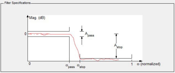
本文主要介绍了基于现场可编程门阵列(fpga)技术fir数字滤波器的设计,设计一个滤波器,其采样率 fs=1MHz,通带截止频率 fpass=50KHz,归一化表示fpass=0.1,阻带起始频率 fstop=200 KHz,归一化表示为fstop=0.4,阻带衰减 80dB。
设计实现
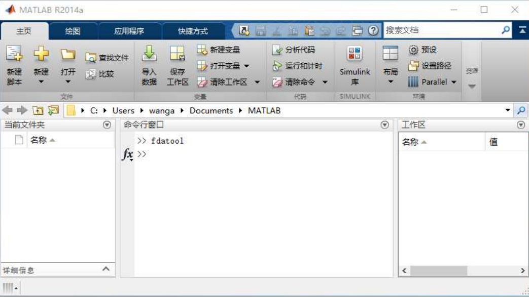
1. 打开 MATLAB 软件,在命令行窗口输入 fdatool 并回车,打开滤波器设计与分析工具窗口
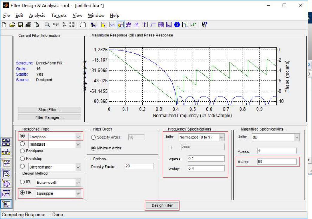
2. 在 fda 工具中配置你需要的滤波器参数
图片中频率参数(frequency specifications)采用的归一化表示方法,如果使用实际频率表示,在 Units 框内选择“KHz”;
在 Fs 内填写 1000,即数字采样频率为1000KHz (1MHz);在 Fpass 内填写 50,即通带截止频率为 50KHz;在 Fstop内填写 200,即阻带起始频率为 200KHz,Astop 填 80,即为阻带衰减 80dB。
点击 Design Filter 后可以查看频率及相位的响应曲线
3.在“Filter Designer & Analysis Tool”界面中,打开 File—>Export…出现下图
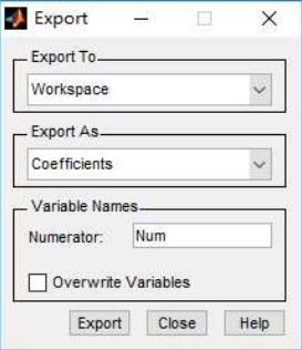
4.点击“Export” 将系数导出到 MATLAB 工作区间
将 coefficients 系数保存到 txt 文件中,在 MATLAB 命令窗口输入:
>> fid=fopen('F:Fpga_ProjectFIR_Filtercoef.txt','w');
% txt 文件路径根据实际情况修改
>> fprintf(fid,'%d,',Num); % 打印到 txt 文件中的相邻系数由逗号隔开
>> fclose(fid);

这样我们就得到了一组滤波器系数,存在上图路径下的 coef.txt 文件中。
打开 quartus prime 17.0 软件,新建工程:
5.工程名字:FIR_Fliter
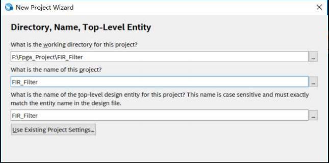
6.选择对应的 FPGA 型号,10M08SCM153C8G

7.根据自己的情况选择 EDA 工具,这里我们选择 synplify pro 和 Modelsim-Altera
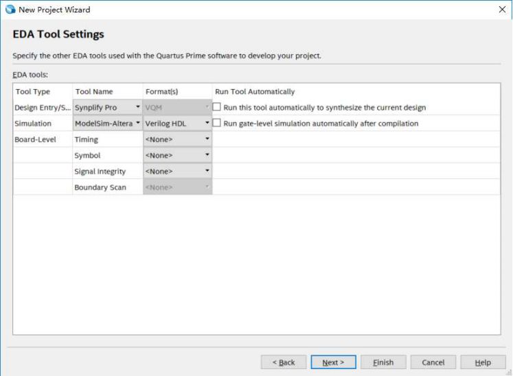
完成新建工程,进入开发界面;
8.在开发界面选择 tools—>IP Catalog,并在 IP Library 中找到 FIR II 的选项,双加 FIR II 打开 QSYS 工具
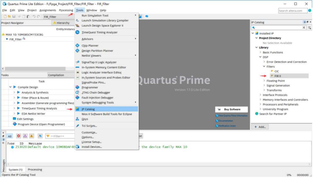
9.填写 IP 实例的名字,点击 OK
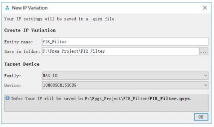
10.在 Filter Specification 选项中配置参数如下图

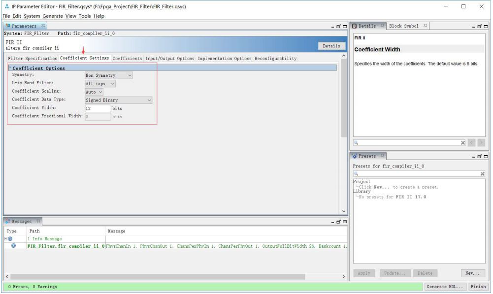
11.在 Coefficient Settings 选项中配置参数如下图
Coefficient width 可以自行配置,一般值越高滤波效果也好,同时实现滤波器消耗的资源也越多
12.在 Coefficients 选项中需要将 Matlab 中导出的滤波系数导入
点击 Import from file 按钮,选择之前从 Matlab 导出的 coef.txt 文件,点击 import 导入;
软件会将导入的系数按照上图中设定的系数位宽调整到合适的值,并分别绘制响应曲线,原始数据 VS 修正数据


13.在 Input/Output Opetion 选项中配置参数
如下图,其中 Input width 根据采样数据的实际位宽填写,这里为 11 位有符号数

14.以上各项参数配置完成后,点击 Generate HDL..,弹出生成页面,点击 Generate,等待完成

通过以上操作完成了 IP 核的生成,点击 Finish 结束。

15.将 IP 核中的 qip 和 sip 文件添加到工程文件列表中
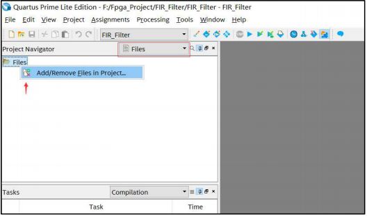

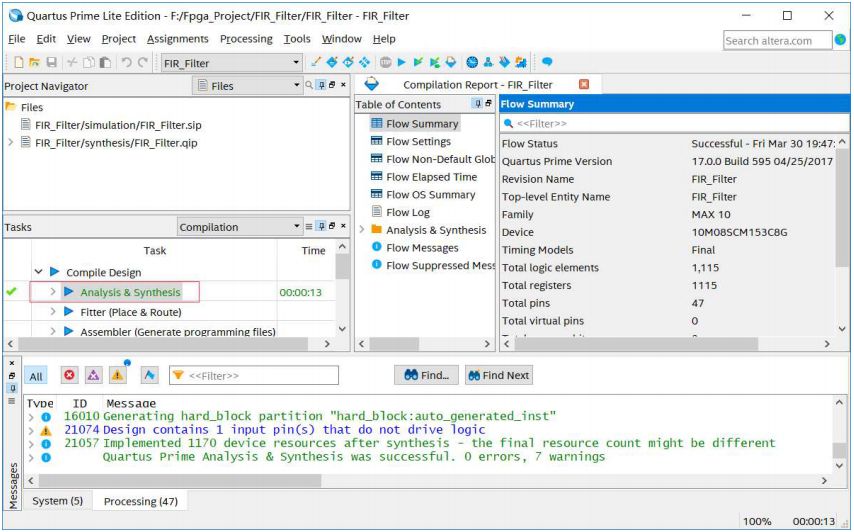
16.对工程进行综合,通过
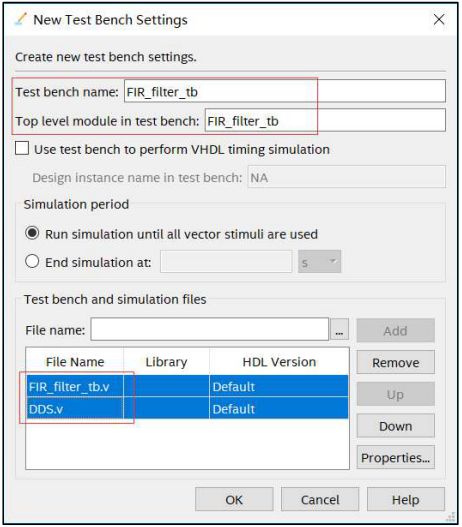
17.将我们准备好的测试文件 FIR_filter_tb.v 和 DDS.v 拷贝至工程目录文件夹下
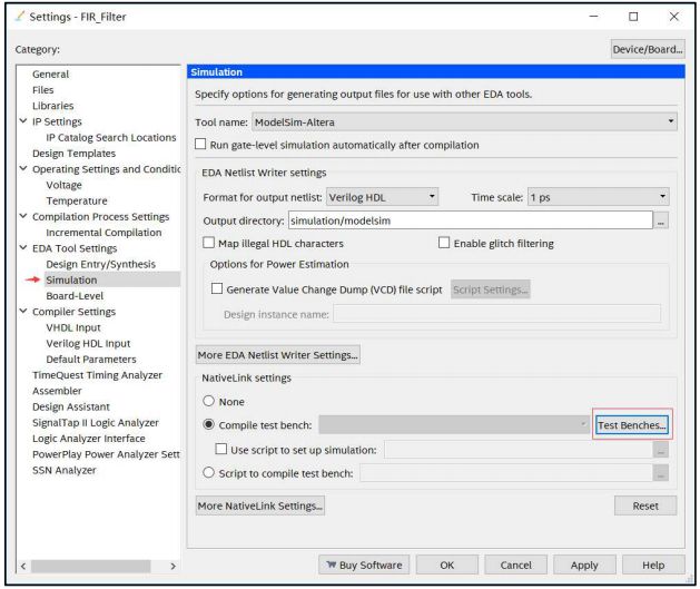
在 Quartus prime 17.0 软件中选择
Assignment —>settings.. —>EDA tool settings —>Simulation —>Test Benches 添加仿真文件
18.点击 Tools —>RUN Simulation Tool —>RTL Simulation
Quartus prime 17.0 支持一键式仿真,直接启动仿真软件 Modelsim-Altera,并显示仿真波形数据(模拟形式显示)
data1 信号为 24KHz 正弦波,量化位宽为 10bit
data2 信号为 240KHz 正弦波,量化位宽为 10bit
data_in 信号为 data1 和 data2 的叠加信号,量化位宽为 11bit
data_out 信号为 data_in 信号经过 FIR 数字滤波后的输出,量化位宽为 28bit
附件一:FIR_filter_tb.v
// --------------------------------------------------------------------
// >>>>>>>>>>>>>>>>>>>>>>>>> COPYRIGHT NOTICE <<<<<<<<<<<<<<<<<<<<<<<<<
// --------------------------------------------------------------------
// Module: FIR_filter_tb
//
// Author: Step
//
// Description: FIR_filter_tb
//
// Web: www.stepfpga.com
//
// --------------------------------------------------------------------
// Code Revision History :
// --------------------------------------------------------------------
// Version: |Mod. Date: |Changes Made:
// V1.1 |2016/10/30 |Initial ver
// --------------------------------------------------------------------
`timescale 1ps/1ps
module FIR_filter_tb;
parameter PERIOD = 20;
reg clk, rst_n;
wire signed [26:0] data_out;
initial begin
clk = 0;
rst_n = 0;
#100;
rst_n = 1;
#6000;
$stop;
end
always #10 clk = ~clk;
wire signed[9:0] data1;
DDS dds_24k
(
.clk_in(clk), //clock in
.rst_n_in(rst_n), //reset, active low
.dds_en_in(1), //dds work enable
.f_increment(24'h60000), //frequency increment
.p_increment(0), //phase increment
.dac_data_out(data1) //data out
);
wire signed[9:0] data2;
DDS dds_240k
(
.clk_in(clk), //clock in
.rst_n_in(rst_n), //reset, active low
.dds_en_in(1), //dds work enable
.f_increment(24'h3c0000), //frequency increment
.p_increment(0), //phase increment
.dac_data_out(data2) //data out
);
wire signed[10:0] data_in = data1 + data2;
FIR_Filter u0 (
.ast_sink_data (data_in), // avalon_streaming_sink.data
.ast_sink_valid (1), // .valid
.ast_sink_error (0), // .error
.ast_source_data (data_out), // avalon_streaming_source.data
.ast_source_valid (), // .valid
.ast_source_error (), // .error
.clk (clk), // clk.clk
.reset_n (rst_n) // rst.reset_n
);
endmodule
附件二:DDS.v
// --------------------------------------------------------------------
// >>>>>>>>>>>>>>>>>>>>>>>>> COPYRIGHT NOTICE <<<<<<<<<<<<<<<<<<<<<<<<<
// --------------------------------------------------------------------
// Module: DDS
//
// Author: Step
//
// Description: DDS
//
// Web: www.stepfpga.com
//
// --------------------------------------------------------------------
// Code Revision History :
// --------------------------------------------------------------------
// Version: |Mod. Date: |Changes Made:
// V1.1 |2016/10/30 |Initial ver
// --------------------------------------------------------------------
module DDS
(
input clk_in, //clock in
input rst_n_in, //reset, active low
input dds_en_in, //dds work enable
input [23:0] f_increment, //frequency increment
input [23:0] p_increment, //phase increment
output dac_clk_out, //clock out
output [9:0] dac_data_out //data out
);
reg [23:0] phase_accumulator;
wire [23:0] phase;
//wire [9:0] dac_data_out;
assign dac_clk_out = clk_in;
//next_phase = phase_accumulator + f_increment;
always @(posedge clk_in or negedge rst_n_in)
begin
if(!rst_n_in) phase_accumulator <= 23'b0;
else if(dds_en_in) phase_accumulator <= phase_accumulator + f_increment;
end
assign phase = phase_accumulator + p_increment; // phase is the high 8 bits
lookup_table lookup_table_uut
(
.phase(phase[23:16]),
.dac_data_out(dac_data_out)
);
endmodule
/**************************************************
module: lookup_table
**************************************************/
module lookup_table
(
input [7:0] phase,
output reg [9:0] dac_data_out
);
wire [5:0] address = phase[5:0];
wire [1:0] sel = phase[7:6];
wire [9:0] sine;
always@(sel or sine)
case (sel)
2'b00 : dac_data_out = {1'b0, sine[9:1]};
2'b01 : dac_data_out = {1'b0, sine[9:1]};
2'b10 : dac_data_out = {1'b1, 9'h1ff-sine[9:1]};
2'b11 : dac_data_out = {1'b1, 9'h1ff-sine[9:1]};
endcase
sine_table sine_table_uut
(
.sel(sel),
.address(address),
.sine(sine)
);
endmodule
/**************************************************
module: sine_table
**************************************************/
module sine_table
(
input [1:0] sel,
input [5:0] address,
output reg [9:0] sine
);
reg [5:0] table_addr;
always @(sel or address)
case (sel)
2'b00: table_addr = address;
2'b01: table_addr = 6'h3f - address;
2'b10: table_addr = address;
2'b11: table_addr = 6'h3f - address;
endcase
always @(table_addr)
case(table_addr)
6'h0: sine=10'h000;
6'h1: sine=10'h019;
6'h2: sine=10'h032;
6'h3: sine=10'h04B;
6'h4: sine=10'h064;
6'h5: sine=10'h07D;
6'h6: sine=10'h096;
6'h7: sine=10'h0AF;
6'h8: sine=10'h0C4;
6'h9: sine=10'h0E0;
6'ha: sine=10'h0F9;
6'hb: sine=10'h111;
6'hc: sine=10'h128;
6'hd: sine=10'h141;
6'he: sine=10'h159;
6'hf: sine=10'h170;
6'h10: sine=10'h187;
6'h11: sine=10'h19F;
6'h12: sine=10'h1B5;
6'h13: sine=10'h1CC;
6'h14: sine=10'h1E2;
6'h15: sine=10'h1F8;
6'h16: sine=10'h20E;
6'h17: sine=10'h223;
6'h18: sine=10'h238;
6'h19: sine=10'h24D;
6'h1a: sine=10'h261;
6'h1b: sine=10'h275;
6'h1c: sine=10'h289;
6'h1d: sine=10'h29C;
6'h1e: sine=10'h2AF;
6'h1f: sine=10'h2C1;
6'h20: sine=10'h2D3;
6'h21: sine=10'h2E5;
6'h22: sine=10'h2F6;
6'h23: sine=10'h307;
6'h24: sine=10'h317;
6'h25: sine=10'h326;
6'h26: sine=10'h336;
6'h27: sine=10'h344;
6'h28: sine=10'h353;
6'h29: sine=10'h360;
6'h2a: sine=10'h36D;
6'h2b: sine=10'h37A;
6'h2c: sine=10'h386;
6'h2d: sine=10'h392;
6'h2e: sine=10'h39C;
6'h2f: sine=10'h3A7;
6'h30: sine=10'h3B1;
6'h31: sine=10'h3BA;
6'h32: sine=10'h3C3;
6'h33: sine=10'h3CB;
6'h34: sine=10'h3D3;
6'h35: sine=10'h3DA;
6'h36: sine=10'h3E0;
6'h37: sine=10'h3E6;
6'h38: sine=10'h3EB;
6'h39: sine=10'h3F0;
6'h3a: sine=10'h3F3;
6'h3b: sine=10'h3F7;
6'h3c: sine=10'h3FA;
6'h3d: sine=10'h3FC;
6'h3e: sine=10'h3FE;
6'h3f: sine=10'h3FF;
endcase
endmodule
-
FPGA
+关注
关注
1634文章
21821浏览量
607479 -
滤波器
+关注
关注
161文章
7909浏览量
179366 -
信号处理器
+关注
关注
1文章
254浏览量
25400
原文标题:【FPGA信号处理一】5分钟学会FIR 滤波器设计
文章出处:【微信号:gh_873435264fd4,微信公众号:FPGA技术联盟】欢迎添加关注!文章转载请注明出处。
发布评论请先 登录
相关推荐
使用FPGA构建的数字滤波器设计方案

基于IP核的FIR低通滤波器该怎么设计?
如何优化FIR数字滤波器?
用CPLD实现FIR数字滤波器的设计
基于LabVIEW的FIR数字滤波器设计

基于MATLAB及FPGA的FIR低通滤波器的设计

基于FPGA的FIR数字滤波器的优化设计

如何使用FPGA实现IIR数字滤波器的设计


 基于现场可编程门阵列(fpga)技术fir数字滤波器的设计


评论