Abstract: The Thermo-Electric Cooler (TEC) is found in many applications that require precision temperature control. The small size of the TEC allows precision thermal control of individual components such as fiber optic laser drivers, precision voltage references, or any other temperature critical device. The temperature-critical components are integrated with a TEC and a temperature monitor into a single thermally-engineered module. An added bonus with TECs is the ability to heat, by reversing the current.
TEC control requires a reversible power source capable of providing positive and negative voltages. To accomplish this from a single supply, an H-bridge circuit can be used. While linear supplies offer low noise, their poor efficiency requires large components and added thermal insulation to prevent the regulator waste heat from loading the cooler. Alternatively, two synchronous buck circuits with complementary drivers provide a higher efficiency supply that can deliver bipolar power from a single positive supply. Forced pulse-width-modulation control of the two output voltages allows current to be sourced and sinked. During current sinking, power is recovered and sent back to the supply line. The MAX1968 is a highly integrated H-bridge PWM switch-mode driver designed for Peltier thermoelectric coolers (TEC) modules.
In 1821, Thomas Seebeck discovered that when two conductors of different materials were joined together in a loop, and a temperature differential was present between the two junctions, a current flowed through the loop. Twelve years later, J. C. Peltier demonstrated the opposite effect -- that by cutting one of the conductors in the loop and forcing a current through the loop, a temperature differential was observed between the two junctions. Due to the materials available at the time, the resistive heat generated by the large currents involved dominated the Peltier effect. Today, with material advances, these junctions have become more practical for use as thermoelectric heat pumps performing the same function as fluorocarbon-based vapor compression refrigeration. While they are still not as efficient as vapor-cycle devices, they have no moving parts or working fluid and can be very small in size.
Because the Peltier effect can be controlled linearly with electricity, the Thermo-Electric Cooler (TEC) has been found in many applications involving precision temperature control. The small size of the TEC has allowed precision thermal control of individual components such as fiber optic laser drivers, precision voltage references or any other temperature critical device. The temperature critical components, a TEC and a temperature monitor are integrated into a single thermally engineered module. An added bonus with TECs is the ability to heat by reversing the current. TEC control requires a reversible power source capable of providing positive and negative voltages. To accomplish this from a single supply an H-bridge circuit can be used. While linear supplies offer low noise, their poor efficiency requires large components and added thermal insulation to prevent the regulator waste heat from loading the cooler. Alternatively, two synchronous buck circuits with complementary drivers provide a higher efficiency supply that can deliver bipolar power from a single positive supply. Forced pulse-width-modulation control of the two output voltages allows current to be sourced and sinked. During current sinking, power is recovered and sent back to the supply line. The MAX1968 is a highly integrated H-bridge PWM switch-mode driver designed for Peltier thermoelectric coolers (TEC) modules.
The MAX1968 is a cost-effective solution for controlling TECs because it integrates the four power switches and the PWM control on a 28 pin thermally enhanced TSSOP-EP package. A metallic slug on the underside of the chip allows the package to dissipate as much as 1.9 Watts and provide bipolar +/-3 Volts at 3 Amps from a single 5 Volts source. Switching is selectable at 500kHz or 1MHz. Independent positive and negative output current limits and a voltage limit are integrated on the chip and can be set using external resistors. An analog control signal precisely sets the TEC current regardless of the TEC voltage. Although the MAX1968 provides a cost and size effective solution for driving a TEC, precision thermal control requires an external control loop.
For precision temperature control, a local monitor inside the TEC module sends temperature information that is compared with a reference, generating an error signal. This error signal is then amplified and sent to the TEC. The TEC then changes the local monitor temperature, completing the loop. Like any control loop, steady state accuracy is related to the DC loop gain. Because of the large thermal mass, it can take tens of seconds for the temperature monitor to respond to TEC changes. Compensation of the TEC and monitor loop can require a slow integrator to avoid oscillations and overshoot. Because the integrator requires large time constants, it can be difficult to find high value capacitors with low enough leakage to achieve high DC gain. Therefore, the smallest size integrator capacitor to achieve stability must be selected.
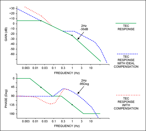
To begin to compensate a thermal loop, the thermal response of the TEC module must be understood. By using the MAX1968 as a driver for the TEC, the internal thermistor in the module and a network analyzer with sub hertz capacity, (like the HP3562A Dynamic Signal Analyzer), the low frequency response of the TEC module can be measured. Most laser diode TEC modules behave approximately as a two-pole system. The first pole starts at 20mHz and a second pole at 1Hz. If a network analyzer is not available, measure the DC gain and use insight to approximate the TEC response. Although this model is crude, it helps us to understand the limitations in closing the loop. Since the modules have a slow 20mHz pole a 90-degree phase shift is expected from the TEC module up to 1 Hz, there after the second pole creates a potentially oscillatory condition. The TEC response in cooling mode is shown graphically with solid lines in Figure 1. Due to the fact that TECs have a four times stronger heating capacity than cooling for the same input current, this response can vary by 6 dB. Other factors such as heat sinking, ambient temperature and heat generated internally in the module can also change the response. Modules from different manufactures can have varying responses as well.

Figure 1.
The Proportional Integral Derivative (PID) controller shown in Figure 2 is a good starting point. From here, adjustments can be made to optimize the TEC response. For the highest DC gain, an integrator is needed. This integrator, formed by C2, adds a third pole which, without R3 (Figure 2), makes stability impossible. R3 inserts a zero into the integrator before unity gain crossover; ideally this should occur at the first pole, 20mHz. It can be pushed up to 70mHz without any stability issues. Although this creates a second order response from 20mHz to 70mHz, the phase never reaches oscillatory conditions (180 Degrees). This is shown with bold dotted lines in Figure 1.

Figure 2.
The differential network, formed by C1, R1 and R2 in Figure 2, adds another zero to cancel the second 1Hz pole in the TEC module. This provides extra phase margin to close the loop at a higher frequency. This is shown graphically in Figure 1 by the dashed lines. While the fast response associated with high loop bandwidth is not needed, the high DC gain and small caps are. The compensator uses C3 to rolloff the gain at 30Hz to reduce noise injection into the loop. In TEC applications this circuit allows the loop to crossover at 2Hz and provides good phase margin over a wide range.
As a compensation example for a 2Hz crossover we refer to the TEC Thermal Loop in Figure 3. Selecting R3 as high as possible allows the smallest integrator capacitor C2. Because we must insert a zero at 70mHz we use the relation

with Fz1 = 70mHz and selecting R3 = 243K it follows that C2 = 9.36uF. We select 10uF. Now we select R1 = 510K. This allows maximum gain in the front-end amplifier (U2) to reduce the reflected integrator (U1) errors.

Figure 3.
Now we must insert a zero to cancel the second pole of the TEC at 1Hz. Because we desire good phase margin we insert the zero at the desired crossover frequency divided by at least 5, or 0.4Hz. This gives a better phase margin at the crossover frequency. We then terminate the zero by at least 5 times the crossover frequency, or 10Hz, using R1. This limits the gain of the integrator section after the loop has crossed over.
Because

and with Fz2 = 0.4Hz and R2 = 510K it follows that C1 = 0.78uF. We select 1uF. To find R1 we use the relation

and with F3 = 10Hz and C1 = 1uF we find that R1 = 15.9K. We use 10K to provide better phase margin.
We then must set the roll-off frequency at 30Hz. With R3 = 243k and Fc = 30Hz and
 ,
,
we find that C3 = 22nF.
Now that the TEC response has been optimized, the system gain must be adjusted for a cross over at 2 Hz. Graphically we can see from Figure 1 that at 2 Hz the uncompensated transfer function (Solid line, Figure 1) has -30 dB gain. If we desire a 2 Hz unity gain cross over we must provide +30 dB gain at 2 Hz. Because the U1 and its components have gain at 2 Hz, we must subtract this gain from the needed system gain to find the front-end gain. At 2 Hz R3 and C1 define the gain for U1. The reactive impedance of C1, can be found using

With C1 = 1uF and Fc = 2 Hz it follows that
Xc = -79.6ki
The gain for U1 is

With R3 = 243k and Xc = -79.6ki, G = 3.05 or 9.7 dB. We now must provide 20.3 dB in the front-end. The front-end gain section, formed by R4, R5 and U2, will also boost the low level signal from the temperature monitor (a 10k at 25C thermistor) and help to overcome the offset errors from the compensation section (U1). With R4 = 10k and R5 = 100k the front-end gain is 11 or 20.8 dB.
The entire loop and the compensation values are shown in Figure 3. This block shows a jumper selectable Digital to Analog Converter (DAC) or a potentiometer to set the TEC module temperature. The temperature set point (SET POINT IN) is subtracted from the temperature monitor (THERM), then amplified and sent to the PID compensation section. Due to the good phase margin provided by the PID compensator this circuit is very tolerant to TEC gain variations in heating or cooling modes.
Selecting components for this circuit will depend on the specific requirement needed. For the U2 and U3, an Op Amp with low offset voltage drift like the MAX4477ASA is a good choice. Because of the low signal level at the thermistor, shielded wire should be used. U1 should have ultra low leakage current to avoid DC offsets generated by the high circuit impedance. The MAX4475ASA with 150 pA maximum leakage current is a good choice. The components around U1, in particular C2 and C3 should be selected with the highest leakage resistance and C2 lowest thermal drift possible. Polystyrene film capacitors are the best choice but they are very large and expensive. Ceramic caps are a good choice, but the larger values can leak sufficiently to cause gain errors. Do not use Electrolytic or Tantalum capacitors. A guard ring constructed with a PC board trace placed around and under the inverting pin on U1 and its components should be connected to the non-inverting pin of U1. The guard ring intercepts any stray currents that can induce errors in the summing junction. Solder flux, moisture and fiberglass PC boards can contribute to leakage currents and a guard ring can improve these effects. Conformal coating the board and its components can help keep contaminates from interfering with circuit performance.
Testing of the loop can be done with a unit step function. A simple change in temperature set point should induce a response in the thermistor that converges on the new temperature set point with very little overshoot. If ringing is observed in the step response, this indicates poor phase margin at the crossover frequency. By noting the ringing frequency and the number of rings, adjustments can be made in the DC gain (crossover frequency) or the compensation circuit (phase margin) until an acceptable response is met. By using this method and some insight into TEC behavior, a TEC loop can be compensated without a network analyzer. Even with the help of a network analyzer, the system should be checked in heating and cooling modes with a unit step response. Heating the TEC in cooling mode and cooling in heating mode presents the worst cases. DC errors in the loop can be measured with a 6 digit meter with 1 gig Ω input impedance like the Agilent 34401A set up to measure the difference between Set Point In and Therm (See Figure 3). This error should be in the 100 uV range. Noise can be measured at the same points with a differential amplifier like the Tektronix ADA400A and a scope. With 100Hz bandwidth, this error should be under 20uV P-P.
Precision thermal control applications will continue to use TECs as a solution. TEC performance can be expected to continue to improve, making them a more attractive solution for a growing range of temperature control applications. TECs may even replace vapor-cycle refrigeration devices used to heat and cool homes. TEC drivers and thermal control loops have only begun to find practical applications.
TEC control requires a reversible power source capable of providing positive and negative voltages. To accomplish this from a single supply, an H-bridge circuit can be used. While linear supplies offer low noise, their poor efficiency requires large components and added thermal insulation to prevent the regulator waste heat from loading the cooler. Alternatively, two synchronous buck circuits with complementary drivers provide a higher efficiency supply that can deliver bipolar power from a single positive supply. Forced pulse-width-modulation control of the two output voltages allows current to be sourced and sinked. During current sinking, power is recovered and sent back to the supply line. The MAX1968 is a highly integrated H-bridge PWM switch-mode driver designed for Peltier thermoelectric coolers (TEC) modules.
In 1821, Thomas Seebeck discovered that when two conductors of different materials were joined together in a loop, and a temperature differential was present between the two junctions, a current flowed through the loop. Twelve years later, J. C. Peltier demonstrated the opposite effect -- that by cutting one of the conductors in the loop and forcing a current through the loop, a temperature differential was observed between the two junctions. Due to the materials available at the time, the resistive heat generated by the large currents involved dominated the Peltier effect. Today, with material advances, these junctions have become more practical for use as thermoelectric heat pumps performing the same function as fluorocarbon-based vapor compression refrigeration. While they are still not as efficient as vapor-cycle devices, they have no moving parts or working fluid and can be very small in size.
Because the Peltier effect can be controlled linearly with electricity, the Thermo-Electric Cooler (TEC) has been found in many applications involving precision temperature control. The small size of the TEC has allowed precision thermal control of individual components such as fiber optic laser drivers, precision voltage references or any other temperature critical device. The temperature critical components, a TEC and a temperature monitor are integrated into a single thermally engineered module. An added bonus with TECs is the ability to heat by reversing the current. TEC control requires a reversible power source capable of providing positive and negative voltages. To accomplish this from a single supply an H-bridge circuit can be used. While linear supplies offer low noise, their poor efficiency requires large components and added thermal insulation to prevent the regulator waste heat from loading the cooler. Alternatively, two synchronous buck circuits with complementary drivers provide a higher efficiency supply that can deliver bipolar power from a single positive supply. Forced pulse-width-modulation control of the two output voltages allows current to be sourced and sinked. During current sinking, power is recovered and sent back to the supply line. The MAX1968 is a highly integrated H-bridge PWM switch-mode driver designed for Peltier thermoelectric coolers (TEC) modules.
The MAX1968 is a cost-effective solution for controlling TECs because it integrates the four power switches and the PWM control on a 28 pin thermally enhanced TSSOP-EP package. A metallic slug on the underside of the chip allows the package to dissipate as much as 1.9 Watts and provide bipolar +/-3 Volts at 3 Amps from a single 5 Volts source. Switching is selectable at 500kHz or 1MHz. Independent positive and negative output current limits and a voltage limit are integrated on the chip and can be set using external resistors. An analog control signal precisely sets the TEC current regardless of the TEC voltage. Although the MAX1968 provides a cost and size effective solution for driving a TEC, precision thermal control requires an external control loop.
For precision temperature control, a local monitor inside the TEC module sends temperature information that is compared with a reference, generating an error signal. This error signal is then amplified and sent to the TEC. The TEC then changes the local monitor temperature, completing the loop. Like any control loop, steady state accuracy is related to the DC loop gain. Because of the large thermal mass, it can take tens of seconds for the temperature monitor to respond to TEC changes. Compensation of the TEC and monitor loop can require a slow integrator to avoid oscillations and overshoot. Because the integrator requires large time constants, it can be difficult to find high value capacitors with low enough leakage to achieve high DC gain. Therefore, the smallest size integrator capacitor to achieve stability must be selected.
To begin to compensate a thermal loop, the thermal response of the TEC module must be understood. By using the MAX1968 as a driver for the TEC, the internal thermistor in the module and a network analyzer with sub hertz capacity, (like the HP3562A Dynamic Signal Analyzer), the low frequency response of the TEC module can be measured. Most laser diode TEC modules behave approximately as a two-pole system. The first pole starts at 20mHz and a second pole at 1Hz. If a network analyzer is not available, measure the DC gain and use insight to approximate the TEC response. Although this model is crude, it helps us to understand the limitations in closing the loop. Since the modules have a slow 20mHz pole a 90-degree phase shift is expected from the TEC module up to 1 Hz, there after the second pole creates a potentially oscillatory condition. The TEC response in cooling mode is shown graphically with solid lines in Figure 1. Due to the fact that TECs have a four times stronger heating capacity than cooling for the same input current, this response can vary by 6 dB. Other factors such as heat sinking, ambient temperature and heat generated internally in the module can also change the response. Modules from different manufactures can have varying responses as well.

Figure 1.
The Proportional Integral Derivative (PID) controller shown in Figure 2 is a good starting point. From here, adjustments can be made to optimize the TEC response. For the highest DC gain, an integrator is needed. This integrator, formed by C2, adds a third pole which, without R3 (Figure 2), makes stability impossible. R3 inserts a zero into the integrator before unity gain crossover; ideally this should occur at the first pole, 20mHz. It can be pushed up to 70mHz without any stability issues. Although this creates a second order response from 20mHz to 70mHz, the phase never reaches oscillatory conditions (180 Degrees). This is shown with bold dotted lines in Figure 1.

Figure 2.
The differential network, formed by C1, R1 and R2 in Figure 2, adds another zero to cancel the second 1Hz pole in the TEC module. This provides extra phase margin to close the loop at a higher frequency. This is shown graphically in Figure 1 by the dashed lines. While the fast response associated with high loop bandwidth is not needed, the high DC gain and small caps are. The compensator uses C3 to rolloff the gain at 30Hz to reduce noise injection into the loop. In TEC applications this circuit allows the loop to crossover at 2Hz and provides good phase margin over a wide range.
As a compensation example for a 2Hz crossover we refer to the TEC Thermal Loop in Figure 3. Selecting R3 as high as possible allows the smallest integrator capacitor C2. Because we must insert a zero at 70mHz we use the relation

with Fz1 = 70mHz and selecting R3 = 243K it follows that C2 = 9.36uF. We select 10uF. Now we select R1 = 510K. This allows maximum gain in the front-end amplifier (U2) to reduce the reflected integrator (U1) errors.

Figure 3.
Now we must insert a zero to cancel the second pole of the TEC at 1Hz. Because we desire good phase margin we insert the zero at the desired crossover frequency divided by at least 5, or 0.4Hz. This gives a better phase margin at the crossover frequency. We then terminate the zero by at least 5 times the crossover frequency, or 10Hz, using R1. This limits the gain of the integrator section after the loop has crossed over.
Because

and with Fz2 = 0.4Hz and R2 = 510K it follows that C1 = 0.78uF. We select 1uF. To find R1 we use the relation

and with F3 = 10Hz and C1 = 1uF we find that R1 = 15.9K. We use 10K to provide better phase margin.
We then must set the roll-off frequency at 30Hz. With R3 = 243k and Fc = 30Hz and
 ,
,we find that C3 = 22nF.
Now that the TEC response has been optimized, the system gain must be adjusted for a cross over at 2 Hz. Graphically we can see from Figure 1 that at 2 Hz the uncompensated transfer function (Solid line, Figure 1) has -30 dB gain. If we desire a 2 Hz unity gain cross over we must provide +30 dB gain at 2 Hz. Because the U1 and its components have gain at 2 Hz, we must subtract this gain from the needed system gain to find the front-end gain. At 2 Hz R3 and C1 define the gain for U1. The reactive impedance of C1, can be found using

With C1 = 1uF and Fc = 2 Hz it follows that
Xc = -79.6ki
The gain for U1 is

With R3 = 243k and Xc = -79.6ki, G = 3.05 or 9.7 dB. We now must provide 20.3 dB in the front-end. The front-end gain section, formed by R4, R5 and U2, will also boost the low level signal from the temperature monitor (a 10k at 25C thermistor) and help to overcome the offset errors from the compensation section (U1). With R4 = 10k and R5 = 100k the front-end gain is 11 or 20.8 dB.
The entire loop and the compensation values are shown in Figure 3. This block shows a jumper selectable Digital to Analog Converter (DAC) or a potentiometer to set the TEC module temperature. The temperature set point (SET POINT IN) is subtracted from the temperature monitor (THERM), then amplified and sent to the PID compensation section. Due to the good phase margin provided by the PID compensator this circuit is very tolerant to TEC gain variations in heating or cooling modes.
Selecting components for this circuit will depend on the specific requirement needed. For the U2 and U3, an Op Amp with low offset voltage drift like the MAX4477ASA is a good choice. Because of the low signal level at the thermistor, shielded wire should be used. U1 should have ultra low leakage current to avoid DC offsets generated by the high circuit impedance. The MAX4475ASA with 150 pA maximum leakage current is a good choice. The components around U1, in particular C2 and C3 should be selected with the highest leakage resistance and C2 lowest thermal drift possible. Polystyrene film capacitors are the best choice but they are very large and expensive. Ceramic caps are a good choice, but the larger values can leak sufficiently to cause gain errors. Do not use Electrolytic or Tantalum capacitors. A guard ring constructed with a PC board trace placed around and under the inverting pin on U1 and its components should be connected to the non-inverting pin of U1. The guard ring intercepts any stray currents that can induce errors in the summing junction. Solder flux, moisture and fiberglass PC boards can contribute to leakage currents and a guard ring can improve these effects. Conformal coating the board and its components can help keep contaminates from interfering with circuit performance.
Testing of the loop can be done with a unit step function. A simple change in temperature set point should induce a response in the thermistor that converges on the new temperature set point with very little overshoot. If ringing is observed in the step response, this indicates poor phase margin at the crossover frequency. By noting the ringing frequency and the number of rings, adjustments can be made in the DC gain (crossover frequency) or the compensation circuit (phase margin) until an acceptable response is met. By using this method and some insight into TEC behavior, a TEC loop can be compensated without a network analyzer. Even with the help of a network analyzer, the system should be checked in heating and cooling modes with a unit step response. Heating the TEC in cooling mode and cooling in heating mode presents the worst cases. DC errors in the loop can be measured with a 6 digit meter with 1 gig Ω input impedance like the Agilent 34401A set up to measure the difference between Set Point In and Therm (See Figure 3). This error should be in the 100 uV range. Noise can be measured at the same points with a differential amplifier like the Tektronix ADA400A and a scope. With 100Hz bandwidth, this error should be under 20uV P-P.
Precision thermal control applications will continue to use TECs as a solution. TEC performance can be expected to continue to improve, making them a more attractive solution for a growing range of temperature control applications. TECs may even replace vapor-cycle refrigeration devices used to heat and cool homes. TEC drivers and thermal control loops have only begun to find practical applications.
 电子发烧友App








评论