Abstract: Use of a hot-swap controller IC provides inrush-current-limiting and circuit-breaker functions for medium to high-voltage circuit protection.
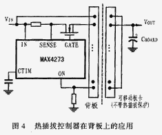
Medium- and high-voltage systems that range from 9V to 72V often require one or more of the following circuit capabilities: hot-swap control, circuit-breaker fault protection, and inrush current limiting.
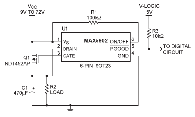
The circuit of Figure 1 provides inrush current limiting and a reliable circuit-breaker function for the load (C1 and R2), yet contains only a p-channel MOSFET, a hot-swap controller IC, and two optional resistors (R1 and R3). Adding a low-value resistor at the MOSFET drain provides an adjustable trip-point and improved accuracy over the operating temperature range (Figure 2).

Figure 1. Standard circuit-breaker application.

Figure 2. Adding a trip-point-adjust resistor (R4) to the circuit of Figure 1 improves its initial accuracy and accuracy over temperature.
For hot-swap applications, U1 limits the inrush current based on a typical gate-drive slew rate of 9V/mS. Inrush current is given by the equation I = CdV/dT = CSR, where C = load capacitance and SR is the slew rate, set by U1 at 9V/mS (typical). For a load capacitance of 100µF, the IC limits inrush current to approximately 0.9A.
U1's circuit-breaker function uses an internal comparator and the MOSFET on-resistance (RDS(ON)) to sense a fault condition. (RDS(ON)) for Q1 is typically 52mΩand U1 has selectable circuit-breaker trip points (CB) of 300mV, 400mV, or 500mV. At the lowest trip point (300mV), the CB trip current at TJ = 25°C is typically 5.77A.
The circuit breaker's voltage-trip value is determined from the equation VCB > (RDS(ON))ILOAD(MAX), or VCB/ILOAD(MAX) > (RDS(ON)).
Suppose the desired limit is 2A. Using typical values,
300mV/2A ≈ 150mΩ > (RDS(ON)).
Instead of substituting another MOSFET with higher on-resistance, add a ≈100mΩ resistor in series with Q1 (i.e., R4 in Figure 2). Besides allowing adjustable circuit-breaker levels, R4 provides better circuit-breaker accuracy and improved stability over temperature. For example, (RDS(ON)) for Q1 is ≈52mΩ @ TJ = 25°C and ≈130mΩ @ TJ=125C, a change of 150%. If you add a 100mΩ, 100ppm/°C resistor (which varies by 0.001Ω from 25°C to 125°C), the combined variance from 25°C (152mΩ) to 125°C (231mΩ) is only 79mΩ, which is 52%.
This former Design Brief was published in the November 10, 2003 issue of ED magazine.
Medium- and high-voltage systems that range from 9V to 72V often require one or more of the following circuit capabilities: hot-swap control, circuit-breaker fault protection, and inrush current limiting.
The circuit of Figure 1 provides inrush current limiting and a reliable circuit-breaker function for the load (C1 and R2), yet contains only a p-channel MOSFET, a hot-swap controller IC, and two optional resistors (R1 and R3). Adding a low-value resistor at the MOSFET drain provides an adjustable trip-point and improved accuracy over the operating temperature range (Figure 2).

Figure 1. Standard circuit-breaker application.

Figure 2. Adding a trip-point-adjust resistor (R4) to the circuit of Figure 1 improves its initial accuracy and accuracy over temperature.
For hot-swap applications, U1 limits the inrush current based on a typical gate-drive slew rate of 9V/mS. Inrush current is given by the equation I = CdV/dT = CSR, where C = load capacitance and SR is the slew rate, set by U1 at 9V/mS (typical). For a load capacitance of 100µF, the IC limits inrush current to approximately 0.9A.
U1's circuit-breaker function uses an internal comparator and the MOSFET on-resistance (RDS(ON)) to sense a fault condition. (RDS(ON)) for Q1 is typically 52mΩand U1 has selectable circuit-breaker trip points (CB) of 300mV, 400mV, or 500mV. At the lowest trip point (300mV), the CB trip current at TJ = 25°C is typically 5.77A.
The circuit breaker's voltage-trip value is determined from the equation VCB > (RDS(ON))ILOAD(MAX), or VCB/ILOAD(MAX) > (RDS(ON)).
Suppose the desired limit is 2A. Using typical values,
Instead of substituting another MOSFET with higher on-resistance, add a ≈100mΩ resistor in series with Q1 (i.e., R4 in Figure 2). Besides allowing adjustable circuit-breaker levels, R4 provides better circuit-breaker accuracy and improved stability over temperature. For example, (RDS(ON)) for Q1 is ≈52mΩ @ TJ = 25°C and ≈130mΩ @ TJ=125C, a change of 150%. If you add a 100mΩ, 100ppm/°C resistor (which varies by 0.001Ω from 25°C to 125°C), the combined variance from 25°C (152mΩ) to 125°C (231mΩ) is only 79mΩ, which is 52%.
This former Design Brief was published in the November 10, 2003 issue of ED magazine.
 电子发烧友App










评论