三角波发生器:Triangle-Wave Generator
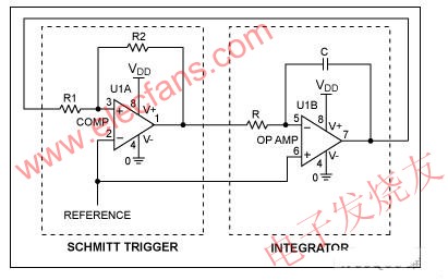
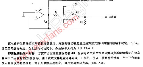
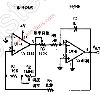
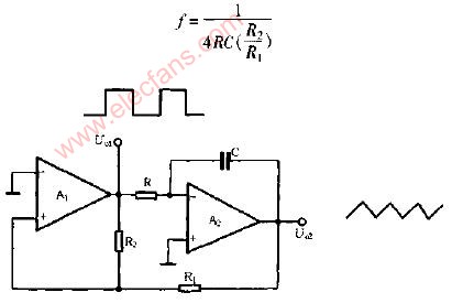
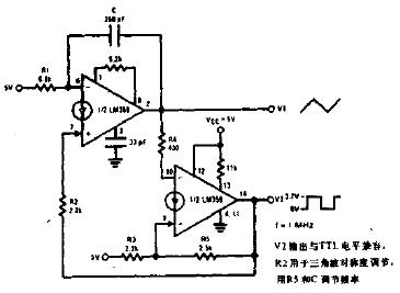
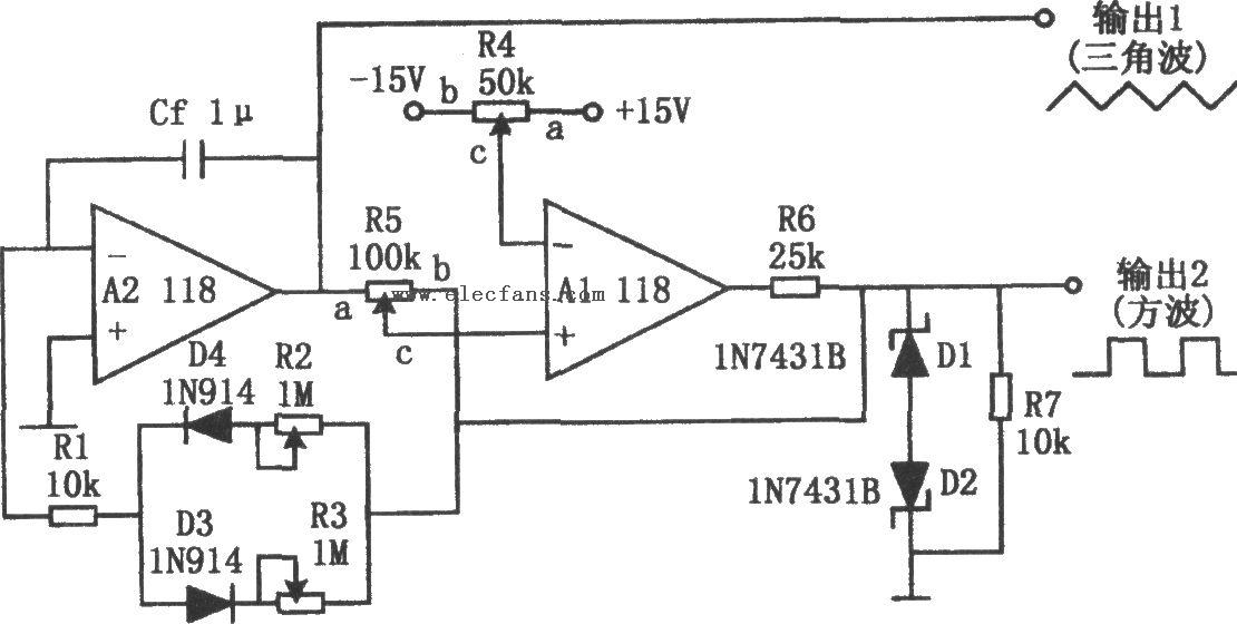
A constant amplitude triangular-wave generator is shown in Figure 27. This circuit provides a variable frequency triangular wave whose amplitude is independent of frequency.
The generator embodies an integrator as a ramp generator and a threshold detector with hysterisis as a reset circuit. The integrator has been described in a previous section and requires no further explanation. The threshold detector is similar to a Schmitt Trigger in that it is a latch circuit with a large dead zone. This function is implemented by using positive feedback around an operational amplifier. When the amplifier output is in either the positive or negative saturated state, the positive feedback network provides a voltage at the non-inverting input which is determined by the attenuation of the feedback loop and the saturation voltage of the amplifier. To cause the amplifier to change states, the voltage at the input of the amplifier must be caused to change polarity by an amount in excess of the amplifier input offset voltage. When this is done the amplifier saturates in the opposite direction and remains in that state until the voltage at its input again reverses. The complete circuit operation may be understood by examining the operation with the output of the threshold detector in the positive state. The detector positive saturation voltage is applied to the integrator summing junction through the combination R3 and R4 causing a current I+ to flow.
The integrator then generates a negative-going ramp with a rate of I+/C1 volts per second until its output equals the negative trip point of the threshold detector. The threshold detector then changes to the negative output state and supplies a negative current, I-, at the integrator summing point. The integrator now generates a positive-going ramp with a rate of I-/C1 volts per second until its output equals the positive trip point of the threshold detector where the detector again changes output state and the cycle repeats. Triangular-wave frequency is determined by R3, R4 and C1 and the positive and negative saturation voltages of the amplifier A1. Amplitude is determined by the ratio of R5 to the combination of R1 and R2 and the threshold detector saturation voltages. Positive and negative ramp rates are equal and positive and negative peaks are equal if the detector has equal positive and negative saturation voltages. The output waveform may be offset with respect to ground if the inverting input of the threshold detector, A1, is offset with respect to ground.
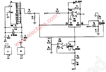
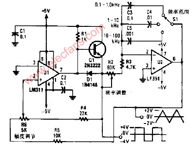
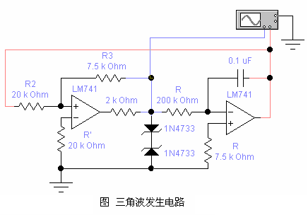
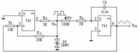
The generator may be made independent of temperature and supply voltage if the detector is clamped with matched zener diodes as shown in Figure 28.
The integrator should be compensated for unity-gain and the detector may be compensated if power supply impedance causes oscillation during its transition time. The current into the integrator should be large with respect to Ibias for maximum symmetry, and offset voltage should be small with respect to VOUT peak.

图27所示电路是一个幅值固定不变的三角波发生器。该电路产生频率可变的三角波信号,但其幅值与频率无关。
此电路用积分器产生斜坡信号,用阈值检测器作为复位电路。积分器前文已详细介绍过,这里不再赘述。阈值检测器就是一种回差范围较大的锁存电路,与施密特触发器相似。电路的功能是通过OP的正反馈路径实现的。不论放大器输出是正是负,只要OP达到输出饱和状态,OP正反馈路径就会在OP同相输入端加上一个电压,该电压的大小由OP正反馈路径的衰减和OP输出饱和时的电压共同决定。为了使放大器的状态发生改变,OP输入端的电压必须改变极性,并且改变量必须大于OP输入失调电压,接着放大器的输出就会改变极性并达到饱和,直到输入端的电压再次反相,再重复这个过程。掌握阈值检测器在正值输出时的工作过程就可以了解整个电路的原理。检测器的正的饱和输出电压通过R3和R4加在积分器的求和节点上,电流为I+。
积分器随即产生由正到负的斜坡信号,斜率为I+/C1(伏/秒)。当这个输出信号达到阈值检测器的低电压门限时,阈值检测器的输出变成负值,加在积分器求和节点的电流反向,变成I-。积分器的输出变成由负到正的斜坡信号,斜率为I-/C1(伏/秒)。当这个输出信号达到阈值检测器的高电压门限时,阈值检测器的输出再次变成正值,至此开始循环。三角波的频率是由R3、R4、C1以及OPA1的饱和输出电压的大小决定的。幅值则等于R5与R1、R2(之和)的比值乘以阈值检测器的饱和输出电压。三角波信号两个斜边的斜率绝对值相等,如果阈值检测器正向饱和电压和反向饱和电压的大小相等,那么三角波信号的正向峰值和反向峰值也相等。如果阈值检测器A1的反相输入端对地有一个偏置电压,那么输出波形也将带有一个对地的偏置。
只要按图28那样在阈值检测器中使用性能匹配的稳压二极管,那么这个信号发生器电路就可以做到与温度变化和电源电压变化无关。
图中积分器所用OP应该是单位增益稳定的,如果电源阻抗导致阈值检测器在输出转换期间发生振荡,那么阈值检测器也需要进行补偿。流入积分器的电流应该大于I bias,以求得最佳的对称性,失调电压也应小于VOUT的峰值。
 电子发烧友App







评论