 电子发烧友App


TI公司的DS90UB960-Q1是多种传感器集线器,能从四个不同的视频数据流通过FPD-Link III接口接收串行化传感器数据.和DS90UB953-Q1配对时,它能以60Hz帧速率接收传感器诸如支持全HD 1080p/2MP分辨率的图像.DS90UB960-Q1包括四个FPD-Link III解串器,每个可通过50-Ω单端同轴或100-Ω差分STP电缆进行连接,而接收均衡器能自动补偿电缆损耗特性,包括随时间的老化.主要用在汽车ADAS如后视照相机(RVC),环绕视图系统(SVS)和照相机监测系统(CMS),前视照相机(FC),驾驶员监测系统(DMS)以及卫星RADAR等以及安全和监控.本文介绍了DS90UB960-Q1主要特性,功能框图,应用电路,以及具有两个4Gbps四路串-并行变换器的ADAS 8路传感器集线器参考设计TIDA-01413主要特性,框图,电路图,材料清单和PCB设计图.
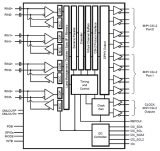
The DS90UB960-Q1 is a versatile sensor hubcapable of connecting serialized sensor data receivedfrom four independent video data streams through anFPD-Link III interface. When paired with aDS90UB953-Q1 serializer, the DS90UB960-Q1receives data from sensors such as imagerssupporting full HD 1080p/2MP resolution at 60-Hzframe rates. Data is received and aggregated into aMIPI CSI-2 compliant output for interconnect to a downstream processor. A second MIPI CSI-2 outputport is available to provide additional bandwidth, oroffers a second replicated output for data-logging andparallel processing.
The DS90UB960-Q1 includes four FPD-Link IIIdeserializers, each enabling a connection throughcost-effective 50-Ω single-ended coaxial or 100-Ωdifferential STP cables. The receive equalizersautomatically adapt to compensate for cable losscharacteristics, including degradation over time.
Each of the FPD-Link III interfaces also includes aseparate low latency bidirectional control channel thatcontinuously conveys I2C, GPIOs, and other controlinformation. General-purpose I/O signals such asthose required for camera synchronization and diagnostics features also make use of thisbidirectional control channel.The DS90UB960-Q1 is AEC-Q100 qualified forautomotive applications and is offered in a costeffectiveand space-saving 64-pin VQFN package.
DS90UB960-Q1主要特性:
1• AEC-Q100 Qualified for Automotive Applications:
– Device Temperature Grade 2: –40℃to +105℃Ambient Operating Temperature Range
• Quad 4.16 GbpsDeserializer Hub AggregatesData From up to 4 Sensors Simultaneously
• Supports 2-Megapixel Sensors With Full HD
1080p Resolution at 60-Hz Frame Rate
• Precise Multi-Camera Synchronization
• MIPI DPHY Version 1.2 / CSI-2 Version 1.3Compliant
– 2 × MIPI CSI-2 Output Ports
– Supports 1, 2, 3, 4 Data Lanes per CSI-2 port
– CSI-2 Data Rate Scalable for 400 Mbps / 800Mbps / 1.2 Gbps / 1.5 Gbps / 1.6 Gbps per Data Lane
– Port Replication Mode
• Ultra-Low Data and Control Path Latency
• Supports Single-Ended Coaxial Including Powerover-Coax (PoC) or Shielded Twisted-Pair (STP)Cable
• Adaptive Receive Equalization
• Dual I2C Ports With Fast-Mode Plus up to 1 Mbps
• Flexible GPIOs for Sensor Synchronization andDiagnostics
• Compatible With DS90UB953-Q1, DS90UB935-Q1,
DS90UB933-Q1, DS90UB913A-Q1Serializers
• Internal Programmable Precision Frame SyncGenerator
• Line Fault Detection and Advanced Diagnostics
DS90UB960-Q1应用:
• Automotive ADAS
– Rear View Cameras (RVC)
– Surround View Systems (SVS)
– Camera Monitoring Systems (CMS)
– Forward Vision Cameras (FC)
– Driver Monitoring Systems (DMS)
– Satellite RADAR, Time-of-Flight (ToF), andLIDAR Sensors Modules
– Sensor Fusion
• Security and Surveillance
![[原创] TI DS90UB960-Q1ADAS 8路传感器集线器参考设计TIDA-01413](/uploads/allimg/180920/15250129D_0.png)
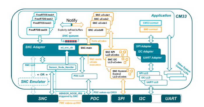
图1.DS90UB960-Q1功能框图
![[原创] TI DS90UB960-Q1ADAS 8路传感器集线器参考设计TIDA-01413](/uploads/allimg/180920/1526019444_0.png)
图2.同轴电缆供电(PoC)系统框图
![[原创] TI DS90UB960-Q1ADAS 8路传感器集线器参考设计TIDA-01413](/uploads/allimg/180920/152F124S_0.png)
图3.典型连接图(同轴)
图4.典型连接图(STP/STQ)
图5.四个DS90UB953-Q1传感器数据连接CSI-2两端口
图6.ADAS系统框图
具有两个4Gbps四路串-并行变换器的ADAS 8路传感器集线器参考设计TIDA-01413
This sensor fusion hub reference design allows theconnection of up to four 2-megapixel cameras and upto four radar modules over coaxial cable. This designutilizes these coaxial cables to provide power, backchannelcommunication, and clock synchronization tothe sensors. The two 4-Gbps FPD-Link III quaddeserializers support dual-outputs of the MobileIndustry Processor Interface (MIPI) Camera SerialInterface-2 (CSI-2) over a Samtec connector toapplication processors.
参考设计TIDA-01413主要特性:
• Accepts 8 High-Speed Data Inputs Over FPD-LinkIII Synchronization Capability
• Provides Wide-Range Supply Voltage for Power
Over Coax (4 V to 14 V)
• Directly Connects to TDA2Plus EVM Through CSI-2 Interface
• Car Battery can Directly Supply Board Power WithProtection From Reverse Current
• Utilizes MSP430™ Microcontroller (MCU) toInitialize and Configure Video Pipeline
• Design Compatible With Onboard MCU, WithoutMCU, or With External MCU
• Works With Any Camera That Uses CompatibleFPD-Link III DS90UB953 Serializer
参考设计TIDA-01413应用:
• Advanced Driver Assistance Systems (ADAS)
• Surround View
• CMS and Mirror Replacement
• ADAS Domain Controller
图7.参考设计TIDA-01413外形图
![[原创] TI DS90UB960-Q1ADAS 8路传感器集线器参考设计TIDA-01413](/uploads/allimg/180920/153201Y63_0.png)
图8.参考设计TIDA-01413框图
图9.参考设计TIDA-01413板顶视图
图10.参考设计TIDA-01413板底视图
![[原创] TI DS90UB960-Q1ADAS 8路传感器集线器参考设计TIDA-01413](/uploads/allimg/180920/1535012058_0.png)
图11.同轴电缆供电框图
![[原创] TI DS90UB960-Q1ADAS 8路传感器集线器参考设计TIDA-01413](/uploads/allimg/180920/153601N36_0.png)
图12.参考设计TIDA-01413电路图(1)
![[原创] TI DS90UB960-Q1ADAS 8路传感器集线器参考设计TIDA-01413](/uploads/allimg/180920/153F13P1_0.png)
图13.参考设计TIDA-01413电路图(2)
![[原创] TI DS90UB960-Q1ADAS 8路传感器集线器参考设计TIDA-01413](/uploads/allimg/180920/153P25X1_0.png)
图14.参考设计TIDA-01413电路图(3)
![[原创] TI DS90UB960-Q1ADAS 8路传感器集线器参考设计TIDA-01413](/uploads/allimg/180920/153Z15421_0.png)
图15.参考设计TIDA-01413电路图(4)
![[原创] TI DS90UB960-Q1ADAS 8路传感器集线器参考设计TIDA-01413](/uploads/allimg/180920/154001TO_0.png)
图16.参考设计TIDA-01413电路图(5)
![[原创] TI DS90UB960-Q1ADAS 8路传感器集线器参考设计TIDA-01413](/uploads/allimg/180920/1541024126_0.png)
图17.参考设计TIDA-01413电路图(6)
![[原创] TI DS90UB960-Q1ADAS 8路传感器集线器参考设计TIDA-01413](/uploads/allimg/180920/154202FL_0.png)
图18.参考设计TIDA-01413电路图(7)
![[原创] TI DS90UB960-Q1ADAS 8路传感器集线器参考设计TIDA-01413](/uploads/allimg/180920/1543011416_0.png)
图19.参考设计TIDA-01413电路图(8)
![[原创] TI DS90UB960-Q1ADAS 8路传感器集线器参考设计TIDA-01413](/uploads/allimg/180920/1544019555_0.png)
图20.参考设计TIDA-01413电路图(9)
![[原创] TI DS90UB960-Q1ADAS 8路传感器集线器参考设计TIDA-01413](/uploads/allimg/180920/1545016318_0.png)
图21.参考设计TIDA-01413电路图(10)
![[原创] TI DS90UB960-Q1ADAS 8路传感器集线器参考设计TIDA-01413](/uploads/allimg/180920/1546011O7_0.png)
图22.参考设计TIDA-01413电路图(11)
![[原创] TI DS90UB960-Q1ADAS 8路传感器集线器参考设计TIDA-01413](/uploads/allimg/180920/154F15424_0.png)
图23.参考设计TIDA-01413电路图(12)
![[原创] TI DS90UB960-Q1ADAS 8路传感器集线器参考设计TIDA-01413](/uploads/allimg/180920/154P2R49_0.png)
图24.参考设计TIDA-01413电路图(13)
图25.参考设计TIDA-01413电路图(14)
参考设计TIDA-01413材料清单:
图26.参考设计TIDA-01413 PCB设计图(1)
图27.参考设计TIDA-01413 PCB设计图(2)
图28.参考设计TIDA-01413 PCB设计图(3)
图29.参考设计TIDA-01413 PCB设计图(4)
图30.参考设计TIDA-01413 PCB设计图(5)
图31.参考设计TIDA-01413 PCB设计图(6)
图32.参考设计TIDA-01413 PCB设计图(7)
图33.参考设计TIDA-01413 PCB设计图(8)
图34.参考设计TIDA-01413 PCB设计图(9)
图35.参考设计TIDA-01413 PCB设计图(10)
图36.参考设计TIDA-01413 PCB设计图(11)
图27.参考设计TIDA-01413 PCB设计图(12)
详情请见:
和
以及
和
与
snls589b.pdf


 工商网监
工商网监
评论