Abstract: This application note highlights the use of the Dallas Semiconductor High-Speed Microcontroller as a bootstrap loader. Example shows a DS87C520 or DS87C530 in conjunction with a 29F010 flash memory in a bootloader configuration.
The most common bootloader configuration incorporates two elements: a microcontroller programmed with the bootstrap loader, or bootloader, and an external memory device such as an NV RAM or Flash memory to hold the user application software. When the system resets following a power-on or external reset, it will begin executing instructions out of the microcontroller's internal program memory. The bootloader code inside the microcontroller begins by checking for a "loader/no-loader"; stimulus such as a logic low on a specific port pin, serial port character, etc. This allows the system to decide if it should load a new user program or if execution should begin using the existing user program. If the stimulus is not received, indicating that no load is desired, the device will disable internal program memory via the ROMSIZE feature and begin execution from external memory. If the stimulus is present, the device will execute the bootloader routine and begin reprogramming the external memory.
This application note will provide examples of how a designer can use an external Flash or NV RAM to add in-system reprogrammability to a High-Speed Microcontroller based design. General hardware and software design guidelines are presented. Software examples to support the techniques described herein are available in electronic format from Dallas Semiconductor via our anonymous FTP site (Internet) or BBS.
An alternate method involves using the serial port to invoke the bootstrap loader. Upon reset, the device can continuously poll the serial port for a character. If a character is not received in a specified period of time, the program will exit the loader and begin execution from the external memory. This approach has the advantage of not requiring a general purpose port pin. Its primary disadvantage is that the device will experience a fixed delay every time it is reset before running the user application.
The ROMSIZE register must be modified from an external memory location that is outside the memory range of internal memory. For example, the DS87C520 contains 16kB of EPROM. The instruction to modify the ROMSIZE register should be located in external memory at an address of 4000h or greater. Failure to do this could result in code execution failure if the memory map switched in the middle of an instruction.
The simplest way to do this is to map a short routine (~16 bytes) at the high end of memory. If a 64kB memory space is used, this could be at FFF0h. This offers the least chance of interfering with the user application code. Upon completion of the loader routine, software will jump to external memory (location FFF0h in this example), modify the ROMSIZE register to disable internal program memory, and then jump to location 0000h. This simulates a reset of the user application code. It is important to include a NOP or other dummy instruction following the modification of the ROMSIZE register to allow one machine cycle for the memory select circuitry to disable the internal program memory. The following routine is suggested:
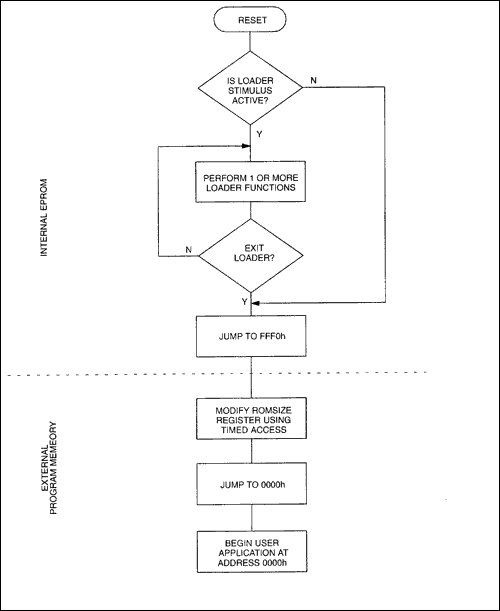
Figure 1 illustrates the basic operation of a bootloader program. The software begins by checking for the signal to start the loader. If present, the device performs user-requested bootloader functions. When complete, or if no loader stimulus was detected, the device will jump to location FFF0h, modify the ROMSIZE register to disable internal EPROM, and jump back to the restart vector. This simulates a device beginning execution at address 0000h following a reset.

Figure 1. Bootloader flowchart.
A sample bootloader for the High-Speed Microcontroller family is available from Dallas Semiconductor. The assembly language source file HSM_LOAD.ASM incorporates optional include files to support several different memory types, including Flash and NV RAM. The following is a list of some of the commands that are supported:

Figure 2. Bootloader hardware.
Although the 29F010 is a 128kB device, this example only uses 64kB by tying the A16 address line low. This will not effect the Flash memory command functions as most devices are designed to ignore A16 during their programming algorithms. To use A16, connect it to an unused general purpose port pin. Be aware that port pins will default to a logic high state, selecting the upper 64kB of Flash memory. An inverter can be used between the port pin and A16 on the Flash device to have it select the lower 64kB on power-up. This will simplify code placement. The "P"; command of the bootloader can be used to manipulate the A16 pin of the Flash memory during the loading process to load both the upper and lower 64kB banks of the device. More information on bank switching can be found in Application Note 81, Memory Expansion with the High-Speed Microcontroller Family.

Figure 3. Bootloader hardware for DS87C520/DS87C530 revision A4.
Overview
Some members of the High-Speed Microcontroller Family incorporate internal EPROM or ROM for program storage. Some applications, however, require in-system reprogrammablility of program memory. Such a system can be easily implemented using the Dallas Semiconductor High-Speed Microcontroller with internal program memory to reload an external nonvolatile memory such as Flash memory or NV RAM. Using the internal program memory as a bootloader allows a lower cost solution than could be obtained by using a device with internal NV RAM program memory or a costly boot-block Flash memory.The most common bootloader configuration incorporates two elements: a microcontroller programmed with the bootstrap loader, or bootloader, and an external memory device such as an NV RAM or Flash memory to hold the user application software. When the system resets following a power-on or external reset, it will begin executing instructions out of the microcontroller's internal program memory. The bootloader code inside the microcontroller begins by checking for a "loader/no-loader"; stimulus such as a logic low on a specific port pin, serial port character, etc. This allows the system to decide if it should load a new user program or if execution should begin using the existing user program. If the stimulus is not received, indicating that no load is desired, the device will disable internal program memory via the ROMSIZE feature and begin execution from external memory. If the stimulus is present, the device will execute the bootloader routine and begin reprogramming the external memory.
This application note will provide examples of how a designer can use an external Flash or NV RAM to add in-system reprogrammability to a High-Speed Microcontroller based design. General hardware and software design guidelines are presented. Software examples to support the techniques described herein are available in electronic format from Dallas Semiconductor via our anonymous FTP site (Internet) or BBS.
Invoking the Bootloader
There are several ways to invoke the loader. The simplest is to dedicate a general purpose I/O pin to be sampled as part of the reset routine contained inside the High-Speed Microcontroller. The examples in this application note utilize P1.7, INT5, because it is least likely to interfere with existing 8051 code designs. Following a reset, the device will begin executing code from internal EPROM. The internal program will perform a quick test of the pin to determine if the loader should be invoked. Because this pin defaults to a high state after reset, it is recommended that a low condition on this pin be used as the signal to invoke the loader. Using an interrupt pin also allows the device to invoke the loader at times other than reset via the interrupt service routine. The method used to assert a logic low can be as simple as a dedicated switch, or a more complicated connection via the RS-232 cable from the host that pulls the pin low when connected.An alternate method involves using the serial port to invoke the bootstrap loader. Upon reset, the device can continuously poll the serial port for a character. If a character is not received in a specified period of time, the program will exit the loader and begin execution from the external memory. This approach has the advantage of not requiring a general purpose port pin. Its primary disadvantage is that the device will experience a fixed delay every time it is reset before running the user application.
Exiting the Bootloader
After loading the new software to external memory, or if loader operation is not desired, the system will need to exit the loader and begin execution from external program memory. The ROMSIZE feature provides a fast and convenient way to do this. The ROMSIZE register allows software to "turn off"; internal program memory and force all program execution externally, similar to pulling the active-low EA pin low. The software should then execute an LJMP to the reset vector at 0000h.The ROMSIZE register must be modified from an external memory location that is outside the memory range of internal memory. For example, the DS87C520 contains 16kB of EPROM. The instruction to modify the ROMSIZE register should be located in external memory at an address of 4000h or greater. Failure to do this could result in code execution failure if the memory map switched in the middle of an instruction.
The simplest way to do this is to map a short routine (~16 bytes) at the high end of memory. If a 64kB memory space is used, this could be at FFF0h. This offers the least chance of interfering with the user application code. Upon completion of the loader routine, software will jump to external memory (location FFF0h in this example), modify the ROMSIZE register to disable internal program memory, and then jump to location 0000h. This simulates a reset of the user application code. It is important to include a NOP or other dummy instruction following the modification of the ROMSIZE register to allow one machine cycle for the memory select circuitry to disable the internal program memory. The following routine is suggested:
CSEG at 0FFF0h
    MOV      TA, #0AAh
    MOV      TA, #55h
    MOV      ROMSIZE, #0h
    NOP
    LJMP     0000h
Bootloader Software
There are many different features that can be included in a bootloader, which vary depending on the specific memory device used. In general, these should include load, verify, and CRC commands. Flash memory devices will require chip erase commands, and an NV RAM may find a fill command useful.Figure 1 illustrates the basic operation of a bootloader program. The software begins by checking for the signal to start the loader. If present, the device performs user-requested bootloader functions. When complete, or if no loader stimulus was detected, the device will jump to location FFF0h, modify the ROMSIZE register to disable internal EPROM, and jump back to the restart vector. This simulates a device beginning execution at address 0000h following a reset.

Figure 1. Bootloader flowchart.
A sample bootloader for the High-Speed Microcontroller family is available from Dallas Semiconductor. The assembly language source file HSM_LOAD.ASM incorporates optional include files to support several different memory types, including Flash and NV RAM. The following is a list of some of the commands that are supported:
- Load Intel Hex file to memory
- Verify Hex file against memory
- Erase chip (Flash only)
- Fill range of memory with data (NV RAM only)
- Calculate CRC
- Modify and read port values
- Dump memory contents in Intel Hex format
- Exit loader
Hardware
Figure 2 illustrates the use of a 29F010 5.0V-only Flash memory as part of a bootloader design. Although this configuration was designed to be compatible with the software presented in the file HSM_LOAD.ASM, it can be easily adapted for other Flash memory or NV RAM devices. Some flash memory devices such as the 28Fxxx series require an external 12V VPP for programming. Designs which incorporate these devices will need to include a voltage source.
Figure 2. Bootloader hardware.
Although the 29F010 is a 128kB device, this example only uses 64kB by tying the A16 address line low. This will not effect the Flash memory command functions as most devices are designed to ignore A16 during their programming algorithms. To use A16, connect it to an unused general purpose port pin. Be aware that port pins will default to a logic high state, selecting the upper 64kB of Flash memory. An inverter can be used between the port pin and A16 on the Flash device to have it select the lower 64kB on power-up. This will simplify code placement. The "P"; command of the bootloader can be used to manipulate the A16 pin of the Flash memory during the loading process to load both the upper and lower 64kB banks of the device. More information on bank switching can be found in Application Note 81, Memory Expansion with the High-Speed Microcontroller Family.
Using NV RAM with the Bootloader
NV RAM has several advantages when used in a bootloader design. It does not require the complicated byte programming algorithm, making it much faster to program. Both data and program can be stored in the same chip, reducing board space while gaining the advantage of data nonvolatility. The use of NV RAMs with internal partitioning, such as the Dallas Semiconductor DS1630 Partitionable 256k NV SRAM or the DS1645 Partitionable 1024k NV SRAM, prevents accidental code corruption. Optional include modules are available for the HSM_LOAD.ASM file to support many Dallas Semiconductor NV RAM products.Addendum for Revision A4 Devices
DS87C520 and DS87C530 devices revision A4 and earlier incorporate an errata pertaining to the active-low PSEN signal that requires a minor change to the above hardware. On these devices, the active-low PSEN signal toggles regardless of whether the device is operating from internal or external program memory. This will cause a conflict during writes to the Flash memory device. Figure 3 illustrates a temporary workaround. This configuration places the restriction that the load signal on P1.7 must be removed before beginning operation from external memory. This is a minor point, as most applications will program the Flash memory in a separate step, reset the device, and then begin operation. This erratum will be corrected on later revisions of the devices.
Figure 3. Bootloader hardware for DS87C520/DS87C530 revision A4.
 电子发烧友App


评论