MAXQ3180入门:寄存器配置
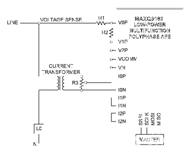
虽然多相、多功能电能计量AFE芯片MAXQ3180具有很多配置寄存器,但仅需配置几个寄存器即可实现基本的测量功能。本篇应用笔记介绍如何成功配置这几个寄存器,列举了必须配置的寄存器,并给出了哪些寄存器必须使能,哪些寄存器不用修改。
简介
MAXQ3180是一款复杂的三相电能计量IC,可在很多计量环境中应用。为了适应各种复杂的计量环境,MAXQ3180共有68个配置寄存器可供修改。正确理解如何使用所有寄存器是一项艰巨任务,但幸运的是在大多数情况下并不需要配置全部68个寄存器。实际上在通常环境下仅需配置10个寄存器即可实现MAXQ3180的基本功能。
本篇应用笔记介绍了必须进行初始化设置的MAXQ3180寄存器,以及在使用特定功能时需要初始化的寄存器,有些寄存器在大多数应用中都可以不设置。
基本初始化过程
MAXQ3180上电后即开始测量电压、电流、功率,计量电能。所以,只有正确配置MAXQ3180,使其与传感器相匹配才能得出正确、有意义的读数。
MAXQ3180执行两步测量:第一步,读取物理参数(如:电压、电流、功率等),在内部用一种“电表单位”表示;第二步,将用“电表单位”表示的参数转换成现实世界中的计量单位,如伏特,安培和瓦。
读取物理参数(计量单位)
MAXQ3180第一步先执行所要求的测量,并在内部用适合测量电路的“电表单位”精确表示,随后的校准过程将确保伏特、安培、瓦、千瓦时等计量单位可以用内部“电表单位”精确表示。一旦电流、电压、功率、电能可以用内部“电表单位”精确表示,器件必须将其转换成有实际意义的单位。
我们以电压校准举例,但其过程也适用于电流、功率和电能。假设一个600:1的电阻分压网络作为输入电路,这意味着600V直流电压作用在电阻分压器输入端,其分压输出约为1V,MAXQ3180的电流和电压输入可分为224级,所以对于600V直流输入,输出编码每改变一个最低有效位(LSB),对应输入电压变化600 × 2-24伏,即35.8µV。换言之,如果输入120VRMS正弦波,则原始RMS电压寄存器读数为120/(600 × 2-24),或3,355,443 (0x33 3333)。
由于输入级用于放大和滤波的无源器件参数以及输入ADC自身参数的离散性,ADC读数有可能和期望值不同,所以,需要输入一个修正系数,该修正系数位于x.V_GAIN (x代表某一相:A、B或C)寄存器。本例中,如果原始RMS寄存器读数为3,000,000 (0x2D C6C0),说明需要的增益为3,355,443/3,000,000 = 1.12。
增益调整寄存器值设为0x4000 (16,384)时增益为1,如需额外增益,则需要增大该值。本例中增益寄存器需设为16,384 × (3,355,443/3,000,000) = 18,325 (0x4795)。
由此完成了第一步,使电压读数能够精确反映以“电表单位”表示的电压测量真实结果。第二步,将一个LSB等于35.8µV的系统转换成一个LSB等于1mV的系统。
计算转换系数
目前遇到的问题是MAXQ3180只提供整数乘法操作,而实现这一转换需要除以一个非整数,即1,000/35.8。解决方案是选取一个系数,使目标单位乘以一个2的整数次幂。在本例中,一个LSB将不再是1mV,而是1mV/216,即15.3nV。所以进行测量时,丢掉低16位,剩下的就是以毫伏表示的电压。
而转换系数就是原始LSB值(35.8µV)除以目标LSB值(15.3nV),即2,344 (0x0928),将该值写入VOLT_CC寄存器。
这样,每次读取V.A虚拟寄存器时,MAXQ3180会将A.VRMS寄存器值乘以2,344,然后报告结果。该结果就是以1mV/65,536为单位的RMS电压值。主机软件丢掉低16位,直接就可以得到以毫伏为单位的RMS电压值。
对于多数应用来说,只需先校准(得到正确的VRMS和IRMS),然后计算转换系数(分别对应于电压、电流、功率和电能)。
其它可选初始化过程
按上述步骤初始化,就可得到电压、电流、电能、功率的精确读数。但MAXQ3180还可提供许多其它功能。
中断
MAXQ3180有一套复杂的中断子系统来通知上位机出现异常,可以触发中断的条件包括:
- 某一相有功或无功电能流向改变。
- 某一相检测到无过零事件时间超过某一阈值。
- 某一相检测到欠压、过压或过流故障。
- 某一相的某一电能寄存器溢出(通常表示需要进行累加操作)。
- 校验和配置发生改变。
- MAXQ3180电源即将失效。
关于中断子系统的更多信息,请参考MAXQ3180的参考设计。
脉冲配置
计量脉冲通常用于递增机械计数器或电能累加寄存器。MAXQ3180能够支持这两种计量脉冲,每一种都有一个配置寄存器用于选择脉冲参数,一个阈值寄存器用于设置电表常数,一个脉冲宽度寄存器用于设置脉冲宽度。关于计量脉冲子系统的更多信息,请参考MAXQ3180的参考设计。
提高精度
使用理想电流和电压传感器,MAXQ3180可以在很宽的输入范围内实现极高精度。但实际上电流传感器很少有理想的,在测量范围的两端会有非线性;通常传感器的相位响应还会随电流变化而改变。需要通过配置MAXQ3180寄存器对其进行补偿以提高精度。
MAXQ3180有两个精确校准机制来补偿传感器的非线性。第一个精确校准机制是在低电流时单独设置增益,在高、低电流下分别设置失调。这样就可以实现高、低电流下增益和失调最多四个点的校准。
第二个精确校准机制是微调电压-电流的相位失调。在这一机制下,通过设置两个阈值将电流范围分成三段。低于两个阈值为第一段,两个阈值之间为第二段,高于两个阈值为第三段。A、B、C每一相的每一段相位失调都可以单独设置。
关于使用精确校准寄存器提高MAXQ3180精度的更多信息请参考MAXQ3180参考设计。
总结
MAXQ3180是一个灵活的电表模拟前端(AFE),具有灵活配置,支持多种电能计量应用。仅需配置少数几个寄存器(主要是校准和增益寄存器),系统即可实现高精度的电能计量功能。
| 图例 | |
| |
该颜色代表在通常应用中必须初始化的寄存器。 |
| |
该颜色代表仅在使用MAXQ3180特定功能时需配置的寄存器,在许多应用中可能无需配置。 |
| |
该颜色代表在大多数应用中无需配置的寄存器。 |
| Address | Default | Name | Comment |
| 0x002 | 0x00 | OPMODE1 | Set this register only if your connection mode is not standard delta or wye, if you wish to reverse pulse output polarity, or if you wish to enable communication CRC. |
| 0x003 | 0x00 | OPMODE2 | This register contains bits for features that are infrequently used. |
| 0x006 | 0x0000 | IRQMASK | Load only if interrupts are used. |
| 0x010 | 0x0000 | AUX_CFG | Load only if the auxiliary channel is used (typically specialized applications). |
| 0x014 | 0x0001 | VOLT_CC | Conversion constant for meter unit to real units conversion. |
| 0x016 | 0x0001 | AMP_CC | Conversion constant for meter unit to real units conversion. |
| 0x018 | 0x0001 | PWR_CC | Conversion constant for meter unit to real units conversion. |
| 0x01A | 0x0001 | ENR_CC | Conversion constant for meter unit to real units conversion. |
| 0x01C | 0x0010 | CYCNT | Load only if the DSP cycle time must be set to something other than 16 line cycles. |
| 0x01E | 0x00 | PLSCFG1 | Load if meter pulses are in use. |
| 0x01F | 0x00 | PLSCFG2 | Load if meter pulses are in use. |
| 0x020 | 0x009C | PLS1_WD | Load if meter pulses are in use. |
| 0x022 | 0x00100000 | THR1 | Load if meter pulses are in use. |
| 0x026 | 0x009C | PLS2_WD | Load if meter pulses are in use. |
| 0x028 | 0x00100000 | THR2 | Load if meter pulses are in use. |
| 0x02C | 0x00C8 | REJ_NS | Line-cycle filter; handle with care! |
| 0x02E | 0x4000 | AVG_NS | Line-cycle filter; handle with care! |
| 0x030 | 0x4000 | AVG_C | Signal-path filter; handle with care! |
| 0x032 | 0x00C8 | HPF_C | Signal-path filter; handle with care! |
| 0x034 | 0x0091 | B0FUND | Fundamental-mode filter; handle with care! |
| 0x036 | 0x000003B6 | A1FUND | Fundamental-mode filter; handle with care! |
| 0x03A | 0x0091 | B0HARM | Harmonic-mode filter; handle with care! |
| 0x03C | 0x000003B6 | A1HARM | Harmonic-mode filter; handle with care! |
| 0x040 | 0x03E80000 | Number of ADC frames per DSP cycle; automatically calculated and seldom needs manual intervention. | |
| 0x044 | 0xFFFF | OCLVL | Load only if overcurrent limits are used. |
| 0x046 | 0xFFFF | OVLVL | Load only if overvoltage limits are used. |
| 0x048 | 0x0000 | UVLVL | Load only if undervoltage limits are used. |
| 0x04A | 0x0003 | NOLOAD | Modify to match with your design specification. |
| 0x054 | 0x2328 | NZX_TIMO | No zero-crossing timeout; generally no need to adjust this. |
| 0x056 | 0x03E8 | COM_TIMO | Communications timeout; generally no need to adjust this. |
| 0x058 | 0x0005 | ACC_TIMO | Energy accumulation startup delay; generally no need to reload this. |
| 0x05A | 0x0B00 | ZC_LPF | Zero-crossing filter; handle with care! |
| 0x05C | 0x0000 | I1THR | Set only if multirange phase compensation is desired. |
| 0x05E | 0x0000 | I2THR | Set only if multirange phase compensation is desired. |
| 0x12E | 0x0000 | N_GAIN | Neutral gain; adjust only if neutral current monitoring is used. |
| 0x130 | 0x0000 | A.I_GAIN | Primary calibration register for phase A current. |
| 0x132 | 0x0000 | A.V_GAIN | Primary calibration register for phase A voltage. |
| 0x134 | 0x0000 | A.E_GAIN | Primary calibration register for phase A energy and power. |
| 0x136 | 0x0000 | A.EF_GAIN | Adjust only if fundamental mode is used. |
| 0x138 | 0x0000 | A.OFFS_HI | Secondary calibration for enhanced accuracy: phase A current offset, high range. |
| 0x13A | 0x0000 | A.GAIN_LO | Secondary calibration for enhanced accuracy: phase A current gain, low range. |
| 0x13C | 0x0000 | A.OFFS_LO | Secondary calibration for enhanced accuracy: phase A current offset, low range. |
| 0x13E | 0x0000 | A.PA0 | Secondary calibration for improved phase compensation. |
| 0x140 | 0x0000 | A.PA1 | Secondary calibration for improved phase compensation. |
| 0x142 | 0x0000 | A.PA2 | Secondary calibration for improved phase compensation. |
| 0x145 | 0x00 | A.MASK | Set only if interrupts from this phase are desired. |
| 0x21C | 0x0000 | B.I_GAIN | Primary calibration register for phase B current. |
| 0x21E | 0x0000 | B.V_GAIN | Primary calibration register for phase B voltage. |
| 0x220 | 0x0000 | B.E_GAIN | Primary calibration register for phase B energy and power. |
| 0x222 | 0x0000 | B.EF_GAIN | Adjust only if fundamental mode is used. |
| 0x224 | 0x0000 | B.OFFS_HI | Secondary calibration for enhanced accuracy: phase B current offset, high range. |
| 0x226 | 0x0000 | B.GAIN_LO | Secondary calibration for enhanced accuracy: phase B current gain, low range. |
| 0x228 | 0x0000 | B.OFFS_LO | Secondary calibration for enhanced accuracy: phase B current offset, low range. |
| 0x22A | 0x0000 | B.PA0 | Secondary calibration for improved phase compensation. |
| 0x22C | 0x0000 | B.PA1 | Secondary calibration for improved phase compensation. |
| 0x22E | 0x0000 | B.PA2 | Secondary calibration for improved phase compensation. |
| 0x231 | 0x00 | B.MASK | Set only if interrupts from this phase are desired. |
| 0x308 | 0x0000 | C.I_GAIN | Primary calibration register for phase C current. |
| 0x30A | 0x0000 | C.V_GAIN | Primary calibration register for phase C voltage. |
| 0x30C | 0x0000 | C.E_GAIN | Primary calibration register for phase C energy and power. |
| 0x30E | 0x0000 | C.EF_GAIN | Adjust only if fundamental mode is used. |
| 0x310 | 0x0000 | C.OFFS_HI | Secondary calibration for enhanced accuracy: phase C current offset, high range. |
| 0x312 | 0x0000 | C.GAIN_LO | Secondary calibration for enhanced accuracy: phase C current gain, low range. |
| 0x314 | 0x0000 | C.OFFS_LO | Secondary calibration for enhanced accuracy: phase C current offset, low range. |
| 0x316 | 0x0000 | C.PA0 | Secondary calibration for improved phase compensation. |
| 0x318 | 0x0000 | C.PA1 | Secondary calibration for improved phase compensation. |
| 0x31A | 0x0000 | C.PA2 | Secondary calibration for improved phase compensation. |
| 0x31D | 0x00 | C.MASK | Set only if interrupts from this phase are desired. |
 电子发烧友App











评论