TI公司的TIDA-01168是四相双向汽车12V/48V电源系统参考设计,采用两个LM5170-Q1电流控制器和TMS320F28027F微控制器(MCU),12V输入电压范围6V-18V, 48V输入电压范围24V-54V,具有反极性,过流和过压以及超温保护,多相可升级选择,输出功率2kW,效率97%,主要用在12V/48V汽车电源分配,超级电容或电池备份电源转换器.本文介绍了LM5170-Q1主要特性,框图,60A双相48V/12V双向转换器应用电路以及参考设计TIDA-01168主要特性和系统指标,框图,电路图,材料清单和PCB设计图.
The LM5170-Q1 controller provides the essential highvoltage and precision elements of a dual-channelbidirectional converter for automotive 48-V and 12-Vdual battery systems. It regulates the average currentflowing between the high voltage and low voltageports in the direction designated by the DIR inputsignal. The current regulation level is programmedthrough analog or digital PWM inputs.
Dual-channel differential current sense amplifiers anddedicated channel current monitors achieve typicalcurrent accuracy of 1%. Robust 5-A half-bridge gatedrivers are capable of driving parallel MOSFETswitches delivering 500 W or more per channel. Thediode emulation mode of the synchronous rectifiersprevents negative currents but also enables discontinuous mode operation for improved efficiencywith light loads. Versatile protection features includecycle-by-cycle current limiting, overvoltage protectionat both HV and LV ports, MOSFET failure detectionand overtemperature protection.
An innovative average current mode control schememaintains constant loop gain allowing a single R-Cnetwork to compensate both buck and boostconversion. The oscillator is adjustable up to 500 kHzand can synchronize to an external clock. Multiphaseparallel operation is achieved by connecting twoLM5170-Q1 controllers for 3- or 4-phase operation, orby synchronizing multiple controllers to phase-shiftedclocks for a higher number of phases. A low state onthe UVLO pin disables the LM5170-Q1 in a low
current shutdown mode.
LM5170-Q1主要特性:
1• AEC-Q100 Qualified for Automotive Applications:
– Device Temperature Grade 1: –40℃ to
+125℃ Ambient Operating Range
– Device HBM ESD Classification Level 2
– Device CDM ESD Classification Level C4B
• 100-V HV-Port and 65-V LV-Port Max Ratings
• 1% Accurate Bidirectional Current Regulation
• 1% Accurate Channel Current Monitoring
• 5-A Peak Half-Bridge Gate Drivers
• Programmable or Adaptive Dead-Time Control
• Programmable Oscillator Frequency With OptionalSynchronization to External Clock
• Independent Channel Enable Control Inputs
• Analog and Digital Channel Current Control Inputs
• Programmable Cycle-by-Cycle Peak Current Limit
• HV and LV Port Overvoltage Protection
• Diode Emulation Prevents Negative Current
• Programmable Soft-Start Timer
• MOSFET Failure Detect at Start-Up and CircuitBreaker Control
• Multiphase Operation Phase Adding or Dropping
LM5170-Q1应用:
• Automotive Dual-Battery Systems
• Super-Cap or Battery Backup Power Converters
• Stackable Buck or Boost Converters

图1.LM5170-Q1功能框图

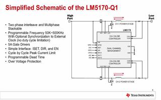
图2.LM5170-Q1简化应用电路图

图3.LM5170-Q1应用电路:60A双相48V/12V双向转换器
参考设计TIDA-01168
The TIDA-01168 reference design is a four-phase, bidirectional DC-DC converter development platform for 12-V/48-V automotive systems. The system uses two LM5170-Q1 current controllers and a TMS320F28027F microcontroller (MCU) for the power stage control. LM5170-Q1 subsystems use average current feedback for current control whereas the C2000™ microcontroller provides voltage feedback. Such a control scheme eliminates phase current balancing typical for multiphase converters. A system based on LM5170-Q1 allows a high level of integration, which reduces printed-circuit board (PCB) area, simplifies design, and speeds up development.
图4.参考设计TIDA-01168外形图
参考设计TIDA-01168主要特性:
12V input voltage range: 6V to 18V
48V input voltage range: 24V to 54V
Reverse polarity, overcurrent overvoltage and overtemperature protection
Multiphase scalable option
Highly integrated solution using automotive qualified components
参考设计TIDA-01168应用:
• In-Vehicle Power Distribution in 12-V/48-VAutomotive Systems
• Supercapacitor or Battery Backup PowerConverters
参考设计TIDA-01168主要系统指标:


图5.参考设计TIDA-01168框图

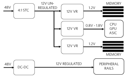
图6.12V和48V汽车电源系统框图

图7.参考设计TIDA-01168电路图(1)

图8.参考设计TIDA-01168电路图(2)

图9.参考设计TIDA-01168电路图(3)

图10.参考设计TIDA-01168电路图(4)

图11.参考设计TIDA-01168电路图(5)

图12.参考设计TIDA-01168电路图(6)

图13.参考设计TIDA-01168电路图(7)

图14.参考设计TIDA-01168电路图(8)

图15.参考设计TIDA-01168电路图(9)

图16.参考设计TIDA-01168电路图(10)

图17.参考设计TIDA-01168电路图(11)

图18.参考设计TIDA-01168电路图(12)

图19.参考设计TIDA-01168电路图(13)

图20.参考设计TIDA-01168电路图(14)
参考设计TIDA-01168材料清单:


图21.参考设计TIDA-01168 PCB设计图(1)

图22.参考设计TIDA-01168 PCB设计图(2)

图23.参考设计TIDA-01168 PCB设计图(3)

图24.参考设计TIDA-01168 PCB设计图(4)

图25.参考设计TIDA-01168 PCB设计图(5)

图26.参考设计TIDA-01168 PCB设计图(6)

图27.参考设计TIDA-01168 PCB设计图(7)

图28.参考设计TIDA-01168 PCB设计图(8)

图29.参考设计TIDA-01168 PCB设计图(9)

图30.参考设计TIDA-01168 PCB设计图(10)
 电子发烧友App






评论