Introduction
Recent breakthroughs in nanotechnology have improved the power density and charge/discharge rates for Lithium ion (Li+) cells. These new capabilities enable applications that require high power density and high charge/discharge rates. These requirements are, of course, in addition to the traditional battery capacities used in portable entertainment and portable computing applications. The high-power cells are ideal for use in power tools and other motor driving applications; they deliver the Li+ advantages plus the NiCd capabilities, together with a low environmental impact (most types qualify for disposal in the regular refuse stream).As technology makes available concentrated energy devices (high energy density) capable of fast delivery (high discharge rate and high power density), safety issues appear. As a reference point, a typical Li+ 4-cell, 2-Ampere-hour (Ah) battery pack stores an energy level of about 100kJ, while a hand grenade (150g of TNT) has 600kJ. The potential for personal injury and/or property damage is clear if such amounts of energy are released in an uncontrolled manner.
Battery safety has several dimensions. Foremost is to prevent personal injury or property damage. There is also the need to protect the equipment that the battery powers. The battery itself must be protected, since it is a fairly expensive part of the system and can be troublesome or hard to replace if it fails. The mechanical, electrical, and chemical design and manufacture of Li+ batteries is a mature technology with its safety issues understood. In recent cases in which Li+ battery failures made world media headlines, contamination of the chemical components seems to have been the root cause of the failures.
Due to some of the safety concerns, battery vendors do not sell single cell Li+ batteries to consumers and even to most OEMs (except for battery-pack manufacturers). Instead, battery vendors offer multicell battery packs as OEM or consumer products. These packs integrate Li+ cells with complex protection electronics. Charging single, randomly selected cells in series or parallel combinations without pack-style protections is not advisable.
Characteristics of Commercially Available Li+ Batteries
Tables 1 and 2 summarize the important characteristics for the range of Li+ batteries available for mass consumer applications. The first battery type in each table is the 18650 interstitial carbon cathode, lithium-cobalt mixed oxide anode, gel electrolyte cell (18mm diameter, 65mm long), one of the most popular types for portable electronics applications. The unit, made by Sony®, is used here as the representative reference to compare with the newer types below. The 18650 cell offers an expected cycle life of 500 charge/discharge cycles, minimum. It retains a capacity of 80% of the nominal value when new (20% capacity fade). Cell capacity is between 0.5Ah and 2Ah.Table 1. Comparison of Temperature Ranges and Charge/Discharge Rates
| Battery Type | Temperature Range (°C) | Max Rates (Current in C Units, Relative to Capacity) |
Charge/Discharge Voltages (Volts) | Cycle Life at 80% Remaining Capacity | ||||||
| Storage | Discharge | Charge | Discharge | Charge | Nominal (Plateau) |
Max Charge (tol. ±1%) | Discharge Cut-off | Do Not Charge | ||
| Sony & Others (Portable Electronics Standard) US18650G4 2Ah (nom), 18mm diam. x 65mm long | -20 to +45 | -20 to +60 | 0 to +45 | 2 | 1 | 3.6 | 4.2 | 3 | < 2.5 | 500 |
| A123 Systems ANR26650M1 2.3Ah (nom), 26mm diam. x 65mm long | -50 to +60 | -30 to +60 | -30 to +60 | 30 52 peak, pulsed. |
4 | 3.3 | 3.6 | 2 | – | > 700 |
| Valence® Technology Saphion® IFR18650p 1.1Ah (nom), 18mm diam. x 65mm long | -40 to +50 | -10 to +50 | 0 to +45 | 18 27 peak, pulsed. |
0.5 | 3.2 | 3.65 | 2 | – | > 600 |
Table 2. Energy and Density Comparison
| Battery Type | Energy Density | Power Density | DC Internal Resistance (mΩ) | ||
| Volumetric (Wh/l) | Gravimetric (Wh/kg) | Volumetric (W/l) | Gravimetric (W/kg) | ||
| Sony & Others (Portable Electronics Standard) US18650G4 2Ah (nom), 18mm diam x 65mm long |
395 | 153 | 832 | 323 | 120 |
| A123 Systems ANR26650M1 2.3Ah (nom), 26mm diam x 65mm long |
200 | 103 | 5800 | 3000 | 20 |
| Valence Technology Saphion IFR18650p 1.1Ah (nom), 18mm diam x 65mm long |
200 | 90 | 4400 | 2000 | 40 |
The maximum charge and discharge rates are defined by the maximum charge and discharge currents relative to the capacity of the battery, expressed in C units. The term "rate" is used since current is the derivative of electric charge to time. The use of rates in place of straight current values allows the specs to be scaled by the capacity, when comparing different battery technologies or different battery sizes for the same technology. For example, a battery subjected to its 1C discharge rate will nominally go from full charge to empty in one hour.
Exceeding the temperature limits of a Li+ battery causes severe loss (fade) of the battery's charge holding ability (capacity). Fade will grow with the time during which the battery remains out of its specified temperature range. The battery will be even more adversely affected if it is discharged or charged under those conditions.
Grossly exceeding the charge/discharge rates will cause the electronic series protection circuit in battery packs to open, triggered by overcurrent (short-term, high current) or overtemperature sensors (long-term). Some of these safety measures can irreversibly disable the battery. Less severe abuses will degrade the battery performance and expected life.
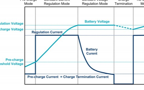
The maximum charge voltage is the tight-tolerance voltage point at which the charge process of a Li+ battery must switch from constant current (CC) to constant voltage (CV). The specification is temperature-independent. Final charge is very sensitive to small changes of this voltage, as Figure 1 implies. Exceeding the charging voltage limit has an irreversible detrimental effect in the battery's charge-retention ability. The combination of both factors imposes a tight tolerance on the charge voltage limit.

Figure 1. The cell-charge characteristics of the Sony US18650G4 Li+ cell show how the battery charges over time and the switchover from the constant-current to the constant-voltage charge mode. Source: Sony Corp.
For a contemporary Li+ battery of the Sony type (see Tables 1 and 2 for other types), if the voltage between terminals is allowed to reach 4.45V, the battery life is compromised.
The charging voltage limit (4.2V for the portable electronics battery type) is the value at which the battery is charged at 100% of its nominal capacity when new. If in the charging process, the CC-to-CV switchover happens at a lower voltage than the nominal charge voltage limit, the charge current will take an early downturn rather than follow the curve in Figure 1. The final stored charge will be considerably less than 100% of nominal capacity.
Violating the cut-off discharge minimum voltage specification has different consequences. If a battery is allowed to discharge below this value, a chemical imbalance is created inside the vessel. If at this point the electrochemical state of the battery is disturbed (i.e., a maximum rate charging is attempted), a sudden abnormal chemical reaction could be triggered that will kill the battery, with a complete loss of the charge-retention ability. All systems developed around a Li+ battery as a power source must include a UVLO (undervoltage lockout) switch to prevent overdischarge, as well as circuitry to prevent high-current charging of deeply discharged cells.
Li+ Battery Charging Methods
With the exception of the voltage source/resistor method used exclusively for very small capacity (a few mAh) Li+ batteries, CCCV (constant current, constant voltage) is the only universally accepted Li+ charging method. A constant current equal to, or lower than, the maximum charge rate is applied to the battery under charge until the maximum charge voltage is reached. At that point the charger operating mode turns to constant voltage output, which is maintained across the battery terminals until the charge termination criterion is satisfied.None of the sophisticated pulse-charge schemes sometimes used with other battery technologies (such as NiCd) reduces full charge time, increases battery life, or the coulometric efficiency of Li+. In most cases those charge schemes have detrimental effects. Trickle charge, the practice of forcing a post-charge long-term small current through the battery to keep it at the full charge state, is not necessary and is also ill-advised with Li+ batteries.
The graph in Figure 1 also shows the behavior of current, voltage, and stored capacity as the charge process progresses in a Sony cell of the type described in Tables 1 and 2. Notice the switchover from CC to CV, and the proportions of the charge acquired by the battery in each phase.
Normal charging termination happens when the battery is fully charged. A popular criterion to determine full charge holds that a Li+ battery is fully charged when the maximum charging voltage has been reached (thus changing the charge mode to CV), and when the falling value of the charge current (happens after the change to CV) is below a certain fraction (usually 1/30 to 1/10) of the battery's maximum charge rate. Another, termination approach uses a timeout, stopping the charging after the charger has been in constant-voltage mode for two hours. No termination action is also sometimes used. In this latter technique the battery is left connected to the charger in constant-voltage mode indefinitely; it is said to be "floating" because there is no current circulating, if the time elapsed is long enough. There is some capacity fade associated with long-term floating, but it is reversible in the first charge cycle.
When any of the battery parameters goes beyond the acceptable range while charging is ongoing, the charger or the pack protection schemes can perform an "abnormal termination" of the charging process. Also, high-end chargers will terminate charging by timeout if any of the expected state transitions (CC→ CV, or CV→ termination) does not happen within a preprogrammed time period.
Li+ Battery-Charger Implementations
Chargers for Li+ batteries come in a large variety of types and technologies, depending on the characteristics of the particular battery type, number of cells in the pack, type of energy source available, and the nature of the application. In all cases the charger is a CCCV power supply, operating in only one quadrant (the charger must not sink current from the battery under any circumstances, powered or nonpowered, etc.), with a highly accurate (better than ±1%) CV output.The efficiency of the charger power supply defines its size (volume and board surface), while the energy source influences the power-supply topology. Decisions among the different power-supply technologies (switching, linear) can be made considering the need for heat dissipation, size, EMI constraints, etc. The key component is the charge controller, an integrated circuit in all cases, which includes the CCCV power supply, the precision reference, and a state machine at a minimum.
More sophisticated chargers include several functions. Examples are: "battery qualification" in which a short-circuit, open, under cutoff, or OK state is detected; sensing the battery temperature; a "prequalification" function in which a small current is applied to the battery until the no-charge voltage level is exceeded; and timeouts for all states of the charger.
Design Examples
At this point it is worthwhile to look at some examples of practical designs for Li+ chargers, from a very simple low-power unit to more complete types with more diverse capabilities. The examples chosen are of the "stand-alone" variety. No separate intelligence or host control is needed to manage the charging.The common characteristic among these examples is the CCCV charge algorithm previously described, with the same accurate CV part, defining the maximum charge voltage, and a medium precision control of the charge CC for all. Since the chip supplier guarantees the CV accuracy, external high-cost precision components are not needed. In all cases both the CC and the CV functions are regulated through the whole range of input voltage.
Differences among the examples consist of:
- The electrical efficiency (the technology and topology used in the chosen IC define it)
- The range (number) of cells that the charger can be set to handle
- The maximum current at which the part can be set in the CC function
- The number and type of protection and automation functions
- The input voltage range
Linear chargers are physically larger, since their lower efficiency generates more heat and thus the need for heatsinking to transfer the heat from the regulator chip. However, the electrical circuitry is simpler than chargers based on switching technology. Switch-mode chargers, nonetheless, do offer higher conversion efficiency and are smaller since they dissipate less heat.
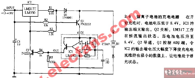
A simple linear charging system, based around the MAX1508, requires only a few extra components (Figure 2). It can supply up to 0.5A to charge a single cell. A self-adaptive power/temperature circuit allows it to operate using a wide range of input voltage and power sources. For multicell charging, a single-switch "switcher" type regulator, the MAX1873, can handle from two to four cells, delivering from 4A to 10A (Figure 3). The circuit also provides an analog voltage readout of the current that is charging the battery.

Figure 2. The MAX1508 is a stand-alone constant-current, constant-voltage (CCCV), thermally regulated linear charger for a single-cell lithium-ion (Li+) battery.

Figure 3. The MAX1873 is a simple switch-mode Li+ charger with an integrated input-current limiting loop.
Offering still more system features, a charger based around the MAX1737 can charge from one to four Li+ cells (Figure 4). The power core is a high-frequency power supply, which keeps the charger size very small. The MAX1737 uses two external power switches (high-side power switch and synchronous rectifier) to achieve higher efficiency and, thus, further reduce any generated heat. The device can monitor battery temperature, has adjustable timeouts for all functions, and can drive LEDs that provide cycle-point indication (full charge, fast charge, fault). The MAX1737's output current capability is defined mostly by the type of external switches used and the external energy source. This controller could support high C rates, even for the higher battery capacities.

Figure 4. The MAX1737 is a switch-mode Li+ battery charger that charges one to four cells. It provides a regulated charging current and a regulated voltage with only a ±0.8% total voltage error at the battery terminals.
References
- Linden & Reddy, Handbook of Batteries, Third Edition, (McGraw-Hill).
- T.R. Crompton, Battery Reference Book, Third Edition, NEWNES.
- Van Schalkwijk and Scrosati, Advances in Lithium-Ion Batteries, KLUWER.
- I. Buchanan, Batteries in a Portable World, Caltex Electronics.
- D. Morrison, Li-Ion Cells Build Better Batteries for Power Tools, Power Electronics Technology (February 06).
Saphion is a registered trademark of Valence Technology, Inc.
Sony is a registered trademark of Kabushiki Kaisha TA Sony Corporation.
Valence is a registered trademark of Valence Technology, Inc.
 电子发烧友App




评论