Abstract: A flyback converter implements a current-limited power supply to charge lead-acid batteries. The MAX773 current-mode controller limits the output current and the flyback transformer provides isolation and flexibility for input voltages both above and below the battery voltage. The MAX471 current-sense amplifier monitors the charging current and feeds back to a threshold detector so that below a designed threshold the flyback converter can switch to a lower charging voltage for trickle-charge mode.
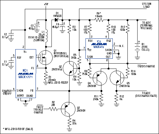
The circuit shown in Figure 1 charges lead-acid batteries in the conventional way: A current-limited power supply maintains a constant voltage across the battery (2.4V/cell or so, as specified by the battery manufacturer) until the charging current decreases below a current threshold defined by the capacity of the battery. At this point, the charger is placed in a trickle-charge mode. The current threshold is typically 0.01C, where C refers to the battery capacity, which is specified in ampere-hours. When charging a battery, the term "C rate" refers to the current required, in theory, to charge a battery to its full battery capacity C in one hour. In actuality, power lost during the charge cycle ensures that all batteries charged at their C rate take more than an hour to reach full charge. Ideally, you could charge a 5A-hr battery in one hour if the charge current is 5A. Also, ideally, a C/10 charge rate (500mA) charges the same battery in 10 hours. However, the power loss mentioned previously increases these charge times beyond the two time spans stated above.

Figure 1. This lead-acid-battery charger applies high voltage (15V) until the battery is charged and then applies 13.8V to maintain a small trickle charge.
The charging voltage involves a trade-off between cell life and charging time. High voltage minimizes the time required, but at full charge it produces a large overcharging current that shortens the battery's life by oxidizing its grid. To save battery life at the expense of charging time, you can lower this current by decreasing the charging voltage.
The ideal compromise is to charge at high voltage until the current drops to 0.01C or so and then lower the voltage to maintain a low trickle-charge current (<0.001C) after the battery is fully charged. The voltage necessary to maintain 0.001C can be determined from the battery manufacturer's "Tafel" curves.
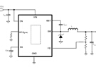
In Figure 1, the boost converter (IC1) applies a constant voltage of nominally 15.2V to the 12V lead-acid battery until it is fully charged. To maintain a trickle charge (overcharging current) of less than 0.001C thereafter, the charging voltage is lowered to about 13.6V. Using a flyback transformer instead of an inductor isolates the battery from VIN and allows VIN to range above and below the charging voltage. To begin a charge cycle, press the Start switch momentarily.
IC2 measures the battery-charging current by generating a smaller (1/2000) but proportional current at the OUT terminal (pin 8). The resulting drop across R2 produces a voltage at IC1 pin 5. When the charging current drops below 0.01C, for instance, this voltage crosses the internal comparator threshold and drives LBO low. By turning off Q2, the feedback level is shifted, which changes the charging voltage to about 13.6V. The maximum available charging current depends on VIN, the transformer's saturation current, and the current-sense resistor R1.
Figure 2 shows the output voltage versus the load current, tested with a resistive load instead of a battery, of the circuit in Figure 1. From right to left, this graph gives the variation of charging current with battery voltage as a battery is charged. At first, the converter is out of regulation, because the battery voltage is less than 12V and therefore is current-limited (supplying maximum current). As the battery voltage rises, the charging current then varies, as shown.

Figure 2. For the circuit in Figure 1, the applied voltage and charging current vary, as shown, during a charge cycle.
The circuit shown in Figure 1 charges lead-acid batteries in the conventional way: A current-limited power supply maintains a constant voltage across the battery (2.4V/cell or so, as specified by the battery manufacturer) until the charging current decreases below a current threshold defined by the capacity of the battery. At this point, the charger is placed in a trickle-charge mode. The current threshold is typically 0.01C, where C refers to the battery capacity, which is specified in ampere-hours. When charging a battery, the term "C rate" refers to the current required, in theory, to charge a battery to its full battery capacity C in one hour. In actuality, power lost during the charge cycle ensures that all batteries charged at their C rate take more than an hour to reach full charge. Ideally, you could charge a 5A-hr battery in one hour if the charge current is 5A. Also, ideally, a C/10 charge rate (500mA) charges the same battery in 10 hours. However, the power loss mentioned previously increases these charge times beyond the two time spans stated above.

Figure 1. This lead-acid-battery charger applies high voltage (15V) until the battery is charged and then applies 13.8V to maintain a small trickle charge.
The charging voltage involves a trade-off between cell life and charging time. High voltage minimizes the time required, but at full charge it produces a large overcharging current that shortens the battery's life by oxidizing its grid. To save battery life at the expense of charging time, you can lower this current by decreasing the charging voltage.
The ideal compromise is to charge at high voltage until the current drops to 0.01C or so and then lower the voltage to maintain a low trickle-charge current (<0.001C) after the battery is fully charged. The voltage necessary to maintain 0.001C can be determined from the battery manufacturer's "Tafel" curves.
In Figure 1, the boost converter (IC1) applies a constant voltage of nominally 15.2V to the 12V lead-acid battery until it is fully charged. To maintain a trickle charge (overcharging current) of less than 0.001C thereafter, the charging voltage is lowered to about 13.6V. Using a flyback transformer instead of an inductor isolates the battery from VIN and allows VIN to range above and below the charging voltage. To begin a charge cycle, press the Start switch momentarily.
IC2 measures the battery-charging current by generating a smaller (1/2000) but proportional current at the OUT terminal (pin 8). The resulting drop across R2 produces a voltage at IC1 pin 5. When the charging current drops below 0.01C, for instance, this voltage crosses the internal comparator threshold and drives LBO low. By turning off Q2, the feedback level is shifted, which changes the charging voltage to about 13.6V. The maximum available charging current depends on VIN, the transformer's saturation current, and the current-sense resistor R1.
Figure 2 shows the output voltage versus the load current, tested with a resistive load instead of a battery, of the circuit in Figure 1. From right to left, this graph gives the variation of charging current with battery voltage as a battery is charged. At first, the converter is out of regulation, because the battery voltage is less than 12V and therefore is current-limited (supplying maximum current). As the battery voltage rises, the charging current then varies, as shown.

Figure 2. For the circuit in Figure 1, the applied voltage and charging current vary, as shown, during a charge cycle.
 电子发烧友App








评论