Abstract: This characterization circuit, plus a PC and some software, accurately measures the full discharge cycle for a rechargeable AA cell. Cell capacity and output resistance can easily be determined from the curve resulting from these measurements.
The proposed characterization circuit, in combination with a PC and AA-Cell Characterizer software, can accurately measure a full discharge cycle. From the resulting curve you can easily determine the cell capacity and output resistance.
The circuit is built around an IC intended for fuel gauging applications in battery packs (DS2751). The DS2751 provides the key components necessary to accurately estimate remaining battery-pack capacity by integrating low-power precision measurements of temperature, voltage, current, and current accumulation (integral of current). This hardware can also record the discharge cycle of a single AA cell (either NiCd or NiMH) with accuracy.

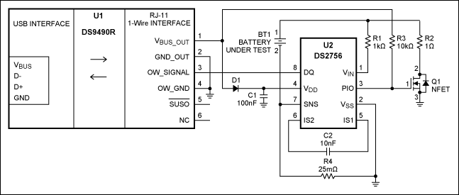
Figure 1. Schematic diagram for an AA-cell discharge characterization circuit.

Figure 2. Software screenshots at startup (a), and during measurement (b).

Put the formula "=(B3-C3)/D3-0.025" into cell E3 and copy it to the rest of column E until the last logged point. Now you can make an x-y graph to show the results. Choosing column 1 for the x values and the other columns for the y values, you will see the cell voltage/current/resistance as a function of discharged current.
Additionally, the user must install Microsoft® .NET Framework version 2.0 and Microsoft Visual J# 2.0 Redistributable Package. Both can be downloaded from the Microsoft website.
Through DQ, a host processor can read/write the registers through the 1-wire protocol. These registers contain the measured data, status information, and certain dedicated information to be stored by the host (manufacturing date, serial number, etc.).
The DS2751 uses "coulomb counting" to measure the amount of charge that goes into and out of the cell. This is achieved by digitally integrating the current (accurately measured) through the sense resistor. The result is stored in the accumulated current register (ACR), and used by the host to calculate the remaining capacity. Because capacity is influenced by cell temperature, a temperature sensor is also included on chip.

Figure 3. Functional block diagram of the DS2751.
The DS2751E+025 includes a 25mΩ sense resistor (the DS2751E requires an external sense resistor). Current is stored as a 12-bit value with 0.625mA resolution and a full-scale range of ±1.9A. The accumulated current is stored as a 16-bit value, with 0.25mAh resolution and a full-scale range of ±8.2Ahr. The maximum voltage allowed is 4.5V, enabling measurement of battery packs with one Li+ cell, or up to three NiMH cells in series.
A similar article appeared in the April, 2006 issue of Elektor Electronics.
Quick View and Data Sheet for the DS2490
Quick View and Data Sheet for the DS2751
1-Wire Software Tools
Samples
Introduction
Rechargeable AA cells are very popular for a large variety of portable applications. The number of brands is also high, and the cell quality can differ considerably. Cell capacity is sometimes different from that specified, and the capacity often deteriorates dramatically after a limited number of discharge cycles.The proposed characterization circuit, in combination with a PC and AA-Cell Characterizer software, can accurately measure a full discharge cycle. From the resulting curve you can easily determine the cell capacity and output resistance.
The circuit is built around an IC intended for fuel gauging applications in battery packs (DS2751). The DS2751 provides the key components necessary to accurately estimate remaining battery-pack capacity by integrating low-power precision measurements of temperature, voltage, current, and current accumulation (integral of current). This hardware can also record the discharge cycle of a single AA cell (either NiCd or NiMH) with accuracy.
Characterization Circuit
In Figure 1, the simple circuit is connected to the USB port of a PC. No external power source is required, because power is extracted from the USB bus voltage. U1 (MAX8881EUT33) is a low-dropout regulator that generates 3.3V for U2 (DS2490S). U2 converts the USB protocol to the 1-Wire® protocol, thereby allowing the PC to communicate with the key circuit component (U3). U3 (DS2751E+025) measures the cell voltage on pin 1 (VIN) through R2, and the cell current through an internal 25mΩ sense resistor between pins 7 (SNS) and 2 (GND). The programmable I/O pin 3 (PIO) allows PC software to control the gate of Q1. When PIO is high, Q1 switches on and loads the cell with R4. That connection causes a discharge current of approximately 1A. When PIO is low, Q1 switches off and removes the cell load.
Figure 1. Schematic diagram for an AA-cell discharge characterization circuit.
Software
AA-Cell Characterizer software, written in Visual Basic, performs the cell discharge cycle. (Note: Please see Drivers and Additional Software before installing this software.) This software initializes U3 and switches off Q1. When you insert a fully charged cell, the software indicates the measured cell voltage (Figure 2a). After you click "Start Measurement", the software switches on Q1 and then logs the cell voltage and current every second. After each logged point, Q1 switches off shortly to allow measurement of the unloaded cell voltage, which is also logged (Figure 2b). To prevent cell damage, the measurement is stopped automatically when the cell voltage drops below 0.8V. After a measurement has been stopped, the "Accumulated current" field shows how much charge has been drawn out of the cell, and gives an indication of the actual capacity. The measurement can also be stopped manually by clicking the "Stop Measurement" button. Clicking "Save Data" saves the logged data to disk for further analysis.
Figure 2. Software screenshots at startup (a), and during measurement (b).
Data Processing
The measured data can be analyzed with an Excel spreadsheet. You can import the log file by clicking "File" and "Open", and then choose "All Files" for the file type. Select the data file, choose "Delimited," and click "Finish." You will see four columns that hold the logged data:- ACR [mAh], the accumulated current in mAh
- V1 [V], the unloaded cell voltage in volts
- V2 [V], the loaded cell voltage in volts
- I [A], the discharge current in amperes

Put the formula "=(B3-C3)/D3-0.025" into cell E3 and copy it to the rest of column E until the last logged point. Now you can make an x-y graph to show the results. Choosing column 1 for the x values and the other columns for the y values, you will see the cell voltage/current/resistance as a function of discharged current.
Important Notes
Drivers and Additional Software
Before installing the AA-Cell Characterizer software, 1-Wire drivers with .NET support must be installed to enable communication between the PC and the DS2490S. These drivers can be downloaded from the Maxim website. After installation, run "default 1-wire net" to find the connected DS2490S, and select the DS2490S as the default 1-Wire net.Additionally, the user must install Microsoft® .NET Framework version 2.0 and Microsoft Visual J# 2.0 Redistributable Package. Both can be downloaded from the Microsoft website.
Other Battery Cells
The circuit can be used for cells other than AA (or A) cells and it can measure multiple cells in series. Always ensure that maximum values are not exceeded. Choose a load resistor of sufficient value that the discharge current does not exceed the DS2751E+025 full-scale range (1.9A). Also make sure that DS2751E+025 pin 1 (VIN) does not exceed the maximum value (4.5V). Use a resistive divider if needed. To prevent damage to the cell, and to yourself, you should also limit the discharge current to approximately C/1h.DS2751
The DS2751 (Figure 3) was developed as a fuel gauge for battery packs.Through DQ, a host processor can read/write the registers through the 1-wire protocol. These registers contain the measured data, status information, and certain dedicated information to be stored by the host (manufacturing date, serial number, etc.).
The DS2751 uses "coulomb counting" to measure the amount of charge that goes into and out of the cell. This is achieved by digitally integrating the current (accurately measured) through the sense resistor. The result is stored in the accumulated current register (ACR), and used by the host to calculate the remaining capacity. Because capacity is influenced by cell temperature, a temperature sensor is also included on chip.

Figure 3. Functional block diagram of the DS2751.
The DS2751E+025 includes a 25mΩ sense resistor (the DS2751E requires an external sense resistor). Current is stored as a 12-bit value with 0.625mA resolution and a full-scale range of ±1.9A. The accumulated current is stored as a 16-bit value, with 0.25mAh resolution and a full-scale range of ±8.2Ahr. The maximum voltage allowed is 4.5V, enabling measurement of battery packs with one Li+ cell, or up to three NiMH cells in series.
A similar article appeared in the April, 2006 issue of Elektor Electronics.
Resources
Quick View and Data Sheet for the MAX8881Quick View and Data Sheet for the DS2490
Quick View and Data Sheet for the DS2751
1-Wire Software Tools
Samples
1-Wire is a registered trademark of Maxim Integrated Products, Inc.
Microsoft is a registered trademark of Microsoft Corp.
 电子发烧友App





评论