| PGA/VGA | PGA |
| Number of channels (#) | 2 |
| Vs (Max) (V) | 5 |
| Vs (Min) (V) | 2.7 |
| Slew rate (Typ) (V/us) | 0.5 |
| Operating temperature range (C) | -40 to 125 |
- Complete Bridge Sensor Conditioner
- Voltage Output: Ratiometric or Absolute
- Digital Cal: No Potentiometers/Sensor Trims
- Sensor Error Compensation
- Span, Offset, and Temperature Drifts
- Low Error, Time-Stable
- Sensor Linearization Circuitry
- Temperature Sense: Internal or External
- Calibration Lookup Table Logic
- Uses External EEPROM (SOT23-5)
- Over/Under-Scale Limiting
- Sensor Fault Detection
- +2.7V TO +5.5V Operation
- –40°C to +125°C Operation
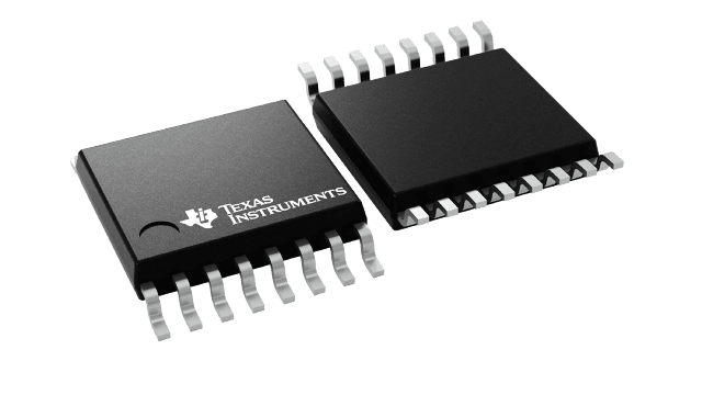
- Small TSSOP-16 Package
- APPLICATIONS
- Bridge Sensors
- Remote 4-20mA Transmitters
- Strain, Load, and Weigh Scales
- Automotive Sensors
- Hardware Designer’s Kit (PGA309EVM)
- Temperature Eval of PGA309 + Sensor
- Full Programming of PGA309
- Sensor Compensation Analysis Tool
All other trademarks are the property of their respective owners.
The PGA309 is a programmable analog signal conditioner designed for bridge sensors. The analog signal path amplifies the sensor signal and provides digital calibration for zero, span, zero drift, span drift, and sensor linearization errors with applied stress (pressure, strain, etc.). The calibration is done via a One-Wire digital serial interface or through a Two-Wire industry-standard connection. The calibration parameters are stored in external nonvolatile memory (typically SOT23-5) to eliminate manual trimming and achieve long-term stability.
The all-analog signal path contains a 2x2 input multiplexer (mux), auto-zero programmable-gain instrumentation amplifier, linearization circuit, voltage reference, internal oscillator, control logic, and an output amplifier. Programmable level shifting compensates for sensor dc offsets.
The core of the PGA309 is the precision, low-drift, no 1/f noise Front-End PGA (Programmable Gain Amplifier). The overall gain of the Front-End PGA + Output Amplifier can be adjusted from 2.7V/V to 1152V/V. The polarity of the inputs can be switched through the input mux to accommodate sensors with unknown polarity output. The Fault Monitor circuit detects and signals sensor burnout, overload, and system fault conditions.
For detailed application information, see the PGA309 User's Guide (SBOU024) available for download at www.ti.com.


