| Number of steps | 64 |
| Number of channels (#) | 2 |
| Resistance taper | Log |
| Interface type | Parallel |
| Memory | Volatile |
| Bandwidth (MHz) | 8 |
| Operating temperature range (C) | -40 to 85 |
- Adjustable Gain From 23.25 dB to –24 dB
- 64-Tap Positions With 0.75 dB Per Step
- Supports 8-MHz Analog Bandwidth
- Operating Range up to –4-V VEE/+4-V VDD
- 100-μA Maximum Static Supply Current
- ±30% End-to-End Resistance Tolerance
- Absolute Tolerance of ±0.3 dB
- Operating Temperature Range From
–40°C to 85°C - ESD Performance Tested Per JESD 22
- 2000-V Human-Body Model
(A114-B,Class II)
- 2000-V Human-Body Model
- APPLICATIONS
- Tandem Adjustable Feedback and Gain
Resistors for Operational Amplifers
- Tandem Adjustable Feedback and Gain
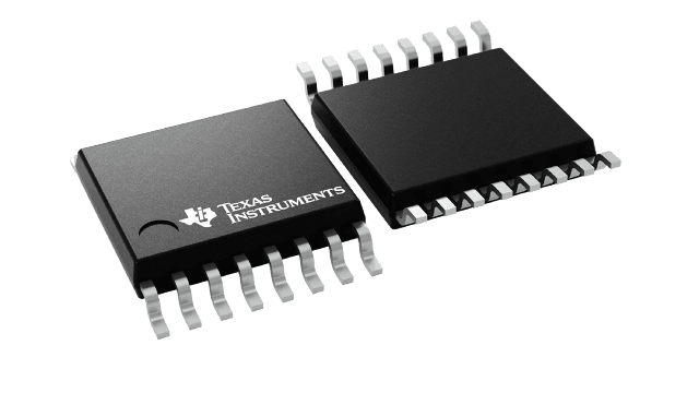
The TPL8002-25 is a programmable resistor device implementing two digital potentiometers with 64 wiper positions each that are tandem controlled through a 6-bit parallel interface. The device has fixed wiper resistances at the respective wiper contacts that tap the potentiometer resistors at a point determined by the binary code present at its digital inputs.
The resistive wiper tap terminals, RSW, of the TPL8002-25 are typically connected to the inverting inputs (–) of an external differential path inverting operational amplifier configuration, with the non-inverting inputs (+) connected through to ground. The application?s differential input to the configuration is the device?s RG terminals. The differential output of the external operational amplifiers is connected to the device?s RF terminals, and thus becomes the differential output of the application configuration.
The resistance between the wiper contacts and the end points RG and RF of the TPL8002-25 provides a logarithmic gain/attenuation response of the configuration. With a digital code of decimal 0 (b000000) the configuration has an inverting maximum attenuation of –24 dB. With a digital code of decimal 32 (b100000) the configuration has inverting unity gain of 0.00 dB. With a digital code of decimal 63 (b111111) the configuration has an inverting maximum gain of +23.25 dB. The response of the configuration with respect to the digital code varies in fixed steps of 0.75 dB.


