| Topology | Flyback, Boost, |
| Duty cycle (Max) (%) | 95 |
| Vin (Max) (V) | 15 |
| UVLO thresholds on/off (V) | 9/8.4 |
| Features | Error Amplifier, Post Regulation, Soft Start, Synchronization Pin |
| Operating temperature range (C) | 0 to 70 |
| Switching frequency (Max) (kHz) | 500 |
| Rating | Catalog |
| Gate drive (Typ) (A) | 1.5 |
- Precision Secondary Side Post Regulation for Multiple Output Power Supplies
- Useful for Both Single Ended and Center Tapped Secondary Circuits
- Ideal Replacement for Complex Magnetic Amplifier Regulated Circuits
- Leading Edge Modulation
- Does Not Require Gate Drive Transformer
- High Frequency (>500kHz) Operation
- Applicable for Wide Range of Output Voltages
- High Current Gate Driver (0.5A Sink/1.5A Source)
- Average Current Limiting Loop
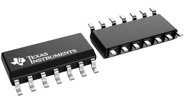
The UCC3583 is a synchronizable secondary side post regulator for precision regulation of the auxiliary outputs of multiple output power supplies. It contains a leading edge pulse width modulator, which generates the gate drive signal for a FET power switch connected in series with the rectifying diode. The turn-on of the power switch is delayed from the leading edge of the secondary power pulse to regulate the output voltage. The UCC3583 contains a ramp generator slaved to the secondary power pulse, a voltage error amplifier, a current error amplifier, a PWM comparator and associated logic, a gate driver, a precision reference, and protection circuitry.
The ramp discharge and termination of the gate drive signal are triggered by the synchronization pulse, typically derived from the falling edge of the transformer secondary voltage. The ramp starts charging again once its low threshold is reached. The gate drive signal is turned on when the ramp voltage exceeds the control voltage. This leading edge modulation technique prevents instability when the UCC3583 is used in peak current mode primary controlled systems.
The controller operates from a floating power supply referenced to the output voltage being controlled. It features an undervoltage lockout (UVLO) circuit, a soft start circuit, and an averaging current limit amplifier. The current limit can be programmed to be proportional to the output voltage, thus achieving foldback operation to minimize the dissipation under short circuit conditions.


