| Display type | LCD unipolar |
| IC integration | VCOM |
| Vin (Min) (V) | 4.5 |
| Vin (Max) (V) | 18 |
| Source driver voltage (Min) (V) | 4.5 |
| Source driver voltage (Max) (V) | 18 |
| Level shifter/scan driver (ch) | 0 |
| Features | Gamma buffer, I2C interface, VCOM or op amp |
| Rating | Catalog |
- I2C Compatible Programmable DAC to Set the Output Current
- Ensured Monotonic DAC
- Non-Volatile Memory to Hold the Setting
- EEPROM in System Programmable
- No External Programming Voltage Required
- Maximum Interface Bus Speed is 400 kHz
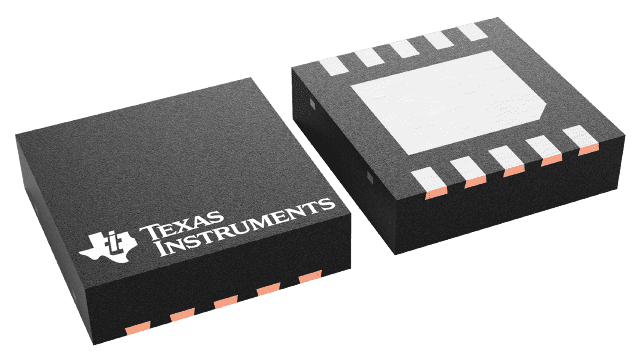
- SON-10 Package
All trademarks are the property of their respective owners.
The LM8342 is an integrated combination of a non-volatile register (7 bits EEPROM) and a DAC controlled current source. Using the LM8342, the VCOM calibration procedure is simplified by elimination of the potentiometer adjustment task. This adjustment task is currently performed at the factory using a trimmer adjustment tool and visual inspection.
The VCOM adjustment can be done electronically in production, using the I2C compatible interface. The factory operator can physically view the screen head-on (frontal viewing) when performing this step, easing manufacturing especially for large TFT panels.
The VCOM level is typically at half AVDD (determined by R1 and R2) and is buffered by the actual VCOM driver. By controlling the level of IOUT, the VCOM level can be tuned. The current level at the output of the LM8342 is a fraction (1/128 to 128/128) of a maximum current which is set by RSET and an analog reference (AVDD). The actual fraction is determined by the 7-bit DAC. As a result, the output current of the LM8342 has a good temperature stability yielding a very stable VCOM adjustment. Controlling the DAC setting of the LM8342 is done via its I2C compatible interface. The actual DAC setting is stored in a volatile register. Using a “Write to EE” command the data can be stored permanently in the embedded EEPROM. At power on of the device, the EEPROM data is copied to the volatile register, setting the DAC. At any time, the data in the EEPROM can be changed again via the I2C compatible interface.


