资料介绍
描述
这是我在 TensorFlow 下使用 Google Summer of Code (GSoC) 的第二个项目。互联网上没有合适的文档来构建自定义图像识别 TinyML 模型,所以我的 GSoC 导师 Paul Ruiz 建议我应该尝试解决它。下面介绍了如何构建图像识别 TinyML 应用程序。快乐修补!
项目背后的理念:
我想解决变量较少的问题,因为有关如何使用相机模块和处理其数据的文档不是很好。我选择构建一个 MNIST TinyML 模型,因为在这种情况下,我不需要担心训练数据集,它可以让我专注于项目的基本部分来启动和运行。但是,既然我已经弄清楚了构建自定义图像识别项目的所有部分,我已经记录了如何使用相机模块收集训练数据集。
博客的主题/基调?
我想警告你,这个博客可能会有点难以理解。对此有一个正确的解释:使用基于加速度计的应用程序,只需在串行监视器或绘图仪上打印出一个轴的加速度计值,就可以很容易地进行完整性检查。相比之下,对图像识别应用程序进行健全性检查至少要麻烦 10 倍,因为无法实时可视化检查一段代码是否正在执行所需的操作。
一些评论
由于单元测试的复杂性,这个博客可能有点难以理解。我想通过读者的反馈来解决解释中的任何空白。因此,请在下面评论您对嵌入式系统图像识别相关的任何疑问和问题。
TinyML 是否有意义?
我建议您阅读TinyML 书的作者 Pete Warden 撰写的这篇精彩文章,以了解为什么在微控制器上运行机器学习模型是有意义的,并且是机器学习的未来。
即使 TinyML 有意义,图像识别在 TinyML 上有意义吗?
我们将在这里使用的 OV7670 相机的完整 VGA(640×480 分辨率)输出对于当前的 TinyML 应用程序来说太大了。uTensor 通过使用 28×28 图像的 MNIST 运行笔迹检测。TensorFlow Lite for Microcontrollers 示例中的人员检测示例使用 96×96,这绰绰有余。即使是最先进的“Big ML”应用程序通常也只使用 320×320 的图像。总之,在微型微控制器上运行图像识别应用程序很有意义
本教程简而言之:
- 集成摄像头和 LCD 模块
- 构建 MNIST TinyML 模型
- 测试 TinyML 模型
- 结论
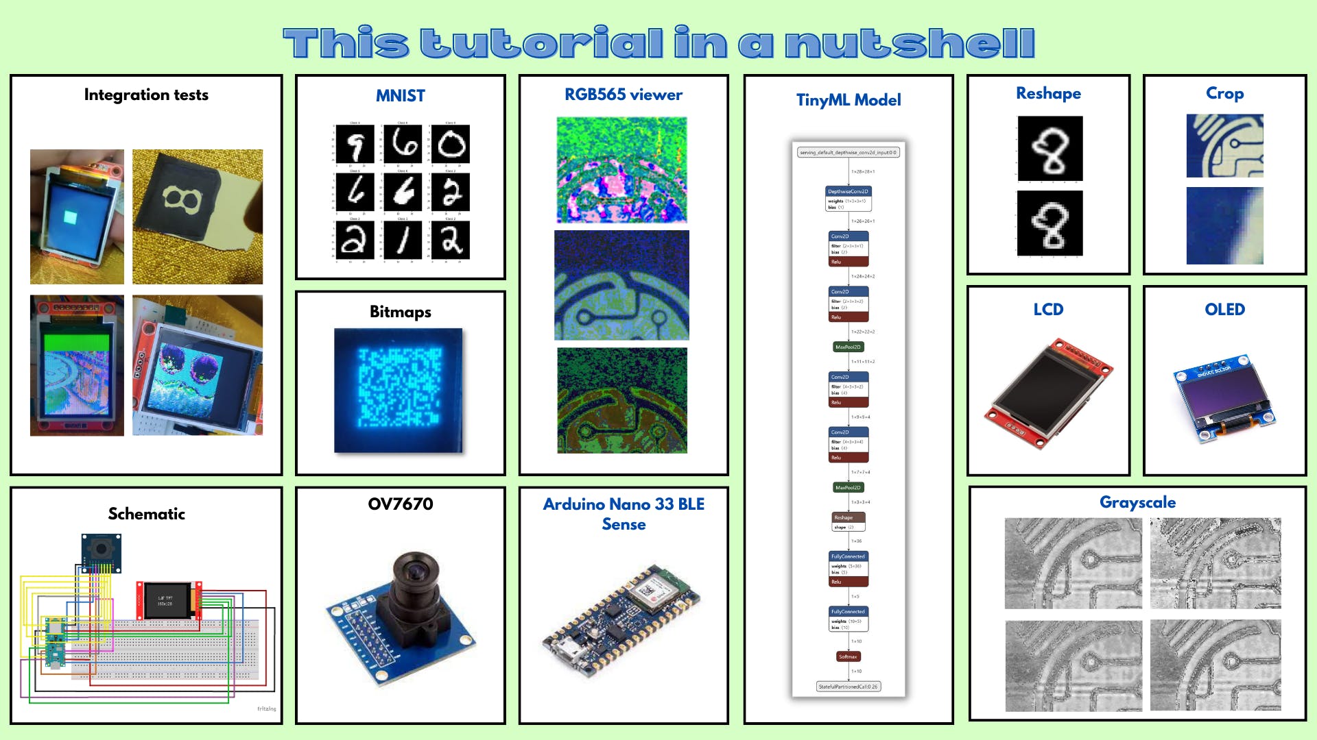
8.集成摄像头和液晶模组
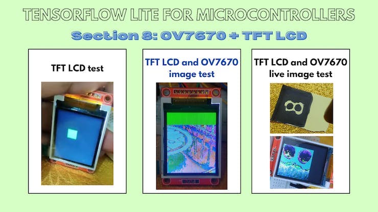
8.a TFT+OV7670:显示测试
本小节的 Github 链接
代码说明:
tft.fillScreen(ST77XX_BLACK);
这行代码用黑色填充屏幕。
for(int i =0; i<28;i++){
    for(int j =0;j<28;j++){
      tft.drawPixel(i,j,ST77XX_GREEN);
      delay(0);
    }
  }
  delay(1000);
这些代码行绘制了一个 28x28 的绿色块。
草图:
#include // Core graphics library
#include // Hardware-specific library for ST7735
#include
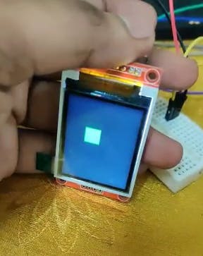
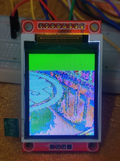
8.b TFT + OV7670:静态图像测试
本小节的 Github 链接。
现在我们已经知道如何显示绿色块,让我们从存储的 HEX 值数组中显示图像。
代码说明:
uint16_t pixels[176 * 144]= {0x0D2A,0xED29,0xED29,0xED29,.....0x95B5,0xB6B5,0xB6B5};
该数组存储所有像素的十六进制值。
for(int i =0; i<50;i++){
    for(int j =0;j<50;j++){
       pixel = pixels[176*i +j];
       tft.drawPixel(i,j,pixel);
}
}
这些代码行通过阵列循环并在 TFT LCD 显示器上绘制图像。
草图:
#include // Core graphics library
#include // Hardware-specific library for ST7735
#include
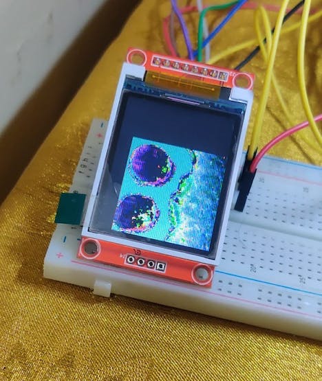
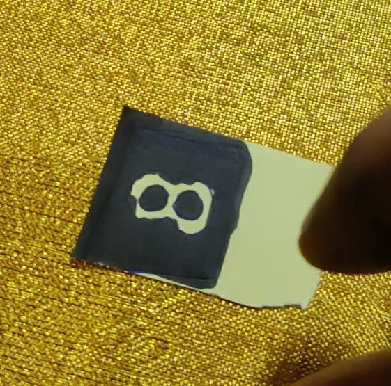
8.c TFT + OV7670:Liveimagetest
本小节的 Github 链接。
现在我们已经知道如何从存储的 HEX 值数组中显示图像,让我们扩展它以显示实时图像。
代码说明:
uint16_t pixels[176 * 144];
这行代码声明了一个数组来存储从相机捕获的图像。
Camera.readFrame(pixels);
这行代码从相机读取一帧并将其存储在像素数组中。
for (int i = 0; i < 112; i++)
{
   for(int j = 0; j < 112; j++)
   {
      uint16_t pixel = pixels[176*i +j];
      tft.drawPixel(i,j,pixel);
   }
}
这些代码行遍历像素阵列并在 TFT LCD 显示器上绘制图像。
草图:
/*
OV767X - Camera Test Pattern
This sketch waits for the letter 'c' on the Serial Monitor,
it then reads a frame from the OmniVision OV7670 camera and
prints the data to the Serial Monitor as a hex string.
The website https://rawpixels.net - can be used the visualize the data:
width: 176
height: 144
RGB565
Little Endian
Circuit:
- Arduino Nano 33 BLE board
- OV7670 camera module:
- 3.3 connected to 3.3
- GND connected GND
- SIOC connected to A5
- SIOD connected to A4
- VSYNC connected to 8
- HREF connected to A1
- PCLK connected to A0
- XCLK connected to 9
- D7 connected to 4
- D6 connected to 6
- D5 connected to 5
- D4 connected to 3
- D3 connected to 2
- D2 connected to 0 / RX
- D1 connected to 1 / TX
- D0 connected to 10
This example code is in the public domain.
*/
#include // Core graphics library
#include // Hardware-specific library for ST7735
#include
9. 构建 MNIST TinyML 模型
注意:如果您是 TensorFlow 或 TinyML 的新手,我强烈建议您通读这篇TinyML 简介博客,以便在深入了解本节之前很好地掌握这些概念。
现在我们已经让相机和显示器工作并集成了,让我们构建机器学习模型来识别数字。
9.a 探索 Colab 笔记本
本小节的 Github 链接。
代码说明:
import numpy as np                   # advanced math library
import matplotlib.pyplot as plt      # MATLAB like plotting routines
import random                        # for generating random numbers

from keras.datasets import mnist     # MNIST dataset is included in Keras
from keras.models import Sequential  # Model type to be used

from keras.layers.core import Dense, Dropout, Activation # Types of layers to be used in our model
from keras.utils import np_utils                         # NumPy related tools
import tensorflow as tf

tf.config.run_functions_eagerly(True)
这些代码行导入必要的库来构建和可视化我们的模型。
(X_train, y_train), (X_test, y_test) = mnist.load_data()
print("X_train shape", X_train.shape)
print("y_train shape", y_train.shape)
print("X_test shape", X_test.shape)
print("y_test shape", y_test.shape)

>>X_train shape (60000, 28, 28)
>>y_train shape (60000,)
>>X_test shape (10000, 28, 28)
>>y_test shape (10000,)
这些代码行加载 MNIST 测试并将图像训练到正确的变量中。
plt.rcParams['figure.figsize'] = (9,9) # Make the figures a bit bigger

for i in range(9):
    plt.subplot(3,3,i+1)
    num = random.randint(0, len(X_train))
    plt.imshow(X_train[num], cmap='gray', interpolation='none')
    plt.title("Class {}".format(y_train[num]))

plt.tight_layout()
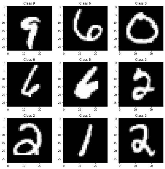
这些代码行从 MNIST 数据集的训练数据中可视化了九个不同的图像。
def matprint(mat, fmt="g"):
    col_maxes = [max([len(("{:"+fmt+"}").format(x)) for x in col]) for col in mat.T]
    for x in mat:
        for i, y in enumerate(x):
            print(("{:"+str(col_maxes[i])+fmt+"}").format(y), end=",")
        print("")

matprint(X_train[num])
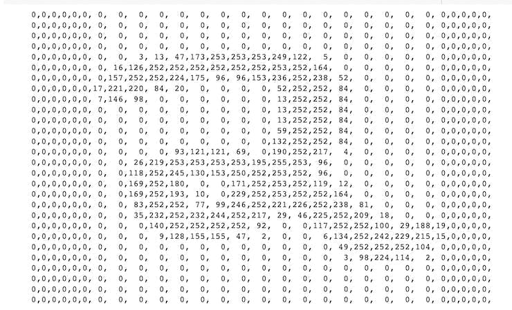
这些代码行将训练数据中的随机图像显示为值数组。
from keras.preprocessing.image import ImageDataGenerator
from keras.layers import Conv2D, MaxPooling2D, ZeroPadding2D, GlobalAveragePooling2D, Flatten
from keras.layers import BatchNormalization
这些代码行导入必要的层来构建机器学习模型。
# Again, do some formatting
# Except we do not flatten each image into a 784-length vector because we want to perform convolutions first

X_train = X_train.reshape(60000, 28, 28, 1) #add an additional dimension to represent the single-channel
X_test = X_test.reshape(10000, 28, 28, 1)

X_train = X_train.astype('float32')         # change integers to 32-bit floating point numbers
X_test = X_test.astype('float32')

#X_train /= 255                              # normalize each value for each pixel for the entire vector for each input
#X_test /= 255

print("Training matrix shape", X_train.shape)
print("Testing matrix shape", X_test.shape)
这些代码行对训练和测试数据进行预处理以使其正常工作,例如:标准化、Float64 到 Float32 的转换和重塑。
# one-hot format classes

nb_classes = 10 # number of unique digits

Y_train = np_utils.to_categorical(y_train, nb_classes)
Y_test = np_utils.to_categorical(y_test, nb_classes)
这些代码行 one-hot 对训练和测试图像的标签进行编码。
from keras.layers.convolutional import DepthwiseConv2D
from keras.backend import relu
from keras.activations import softmax
model = Sequential()                                 # Linear stacking of layers

model.add(DepthwiseConv2D((3,3),input_shape=(28,28,1)))
# Convolution Layer 1
model.add(Conv2D(2, (3, 3)))      # 2 different 3x3 kernels -- so 2 feature maps
model.add(BatchNormalization(axis=-1))               # normalize each feature map before activation
convLayer1 = Activation('relu')                     # activation
model.add(convLayer1)

# Convolution Layer 2
model.add(Conv2D(2, (3, 3)))                        # 2 different 3x3 kernels -- so 2 feature maps
model.add(BatchNormalization(axis=-1))               # normalize each feature map before activation
model.add(Activation('relu'))                        # activation
convLayer2 = MaxPooling2D(pool_size=(2,2))          # Pool the max values over a 2x2 kernel
model.add(convLayer2)

# Convolution Layer 3
model.add(Conv2D(4,(3, 3)))                         # 4 different 3x3 kernels -- so 4 feature maps
model.add(BatchNormalization(axis=-1))               # normalize each feature map before activation
convLayer3 = Activation('relu')                     # activation
model.add(convLayer3)

# Convolution Layer 4
model.add(Conv2D(4, (3, 3)))                        # 4 different 3x3 kernels -- so 64 feature maps
model.add(BatchNormalization(axis=-1))               # normalize each feature map before activation
model.add(Activation('relu'))                        # activation
convLayer4 = MaxPooling2D(pool_size=(2,2))          # Pool the max values over a 2x2 kernel
model.add(convLayer4)

model.add(Flatten())
model.add(Dense(5,activation = relu))
model.add(Dense(10, activation = softmax))
这些代码行定义了机器学习模型中的实际层。
model.summary()
这行代码向用户显示有关模型架构的信息。
model.compile(loss='categorical_crossentropy', optimizer='adam', metrics=['accuracy'])
这行代码定义了机器学习模型在训练时要使用的损失、优化器和其他指标。
history = model.fit(X_train,Y_train, steps_per_epoch=60000//128, epochs=3, verbose=1,
                    validation_data=(X_test,Y_test))
这行代码训练机器学习模型。
score = model.evaluate(X_test, Y_test)
print('Test score:', score[0])
print('Test accuracy:', score[1])
这些代码行评估机器学习模型并将准确性和分数打印给用户。
!apt-get -qq install xxd
converter = tf.lite.TFLiteConverter.from_keras_model(model)
tflite_model = converter.convert()

# Save the model to disk
open("gesture_model.tflite", "wb").write(tflite_model)

import os
basic_model_size = os.path.getsize("gesture_model.tflite")
print("Model is %d bytes" % basic_model_size)
这些代码行将 TensorFlow 模型转换为 TensorFlow Lite 模型。
!echo "const unsigned char model[] = {" > /content/model.h
!cat gesture_model.tflite | xxd -i      >> /content/model.h
!echo "};"                              >> /content/model.h

import os
model_h_size = os.path.getsize("model.h")
print(f"Header file, model.h, is {model_h_size:,} bytes.")
print("\nOpen the side panel (refresh if needed). Double click model.h to download the file.")
这些代码行将 TensorFlow Lite 模型转换为 C 文件以供微控制器使用。

现在我们已经构建并训练了我们的模型,我们现在需要弄清楚如何将数据从相机发送到 TinyML 模型。
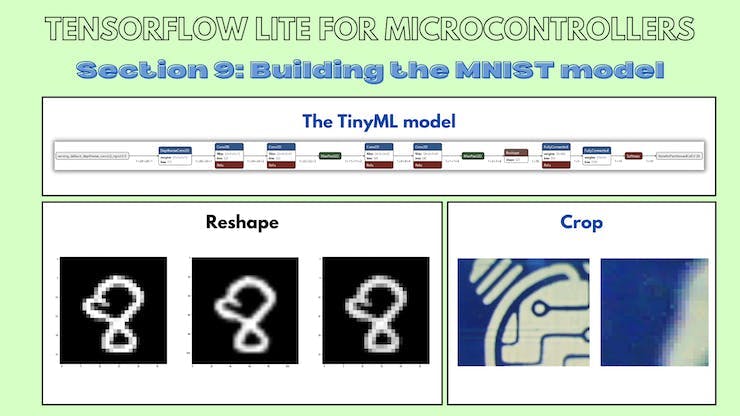
相机的输出尺寸为 176x144,模型的输入尺寸为 28x28。我们可以尝试两种方法:
- 1. 从相机的输出中裁剪出 28x28 的图像。
- 2. 从相机的输出中裁剪出 128x128 的图像并将其重新整形为 28x28
我们将在以下部分尝试这两种方法。
9.b OV7670:作物测试
本小节的 Github 链接。
代码说明:
uint16_t pixels[176 * 144]= {0x0D2A,0xED29,0xED29,0xED29,....,0xB5AD,0x95B5,0xB6B5,0xB6B5};
这行代码将 HEX 值存储在大小为 176X144 的数组中。
for(int a = 0; a< 112; a++)
   {
    for(int b = 0; b< 112; b++)
    {
      Serial.print( pixels[176*a +b]);
      Serial.print(", ");
    }
    Serial.println("");
   }
这些代码行遍历数组并打印出图像的前 28x28 像素。
草图:
/*
  OV767X - Camera Test Pattern

  This sketch waits for the letter 'c' on the Serial Monitor,
  it then reads a frame from the OmniVision OV7670 camera and
  prints the data to the Serial Monitor as a hex string.

  The website https://rawpixels.net - can be used the visualize the data:
    width: 176
    height: 144
    RGB565
    Little Endian

  Circuit:
    - Arduino Nano 33 BLE board
    - OV7670 camera module:
      - 3.3 connected to 3.3
      - GND connected GND
      - SIOC connected to A5
      - SIOD connected to A4
      - VSYNC connected to 8
      - HREF connected to A1
      - PCLK connected to A0
      - XCLK connected to 9
      - D7 connected to 4
      - D6 connected to 6
      - D5 connected to 5
      - D4 connected to 3
      - D3 connected to 2
      - D2 connected to 0 / RX
      - D1 connected to 1 / TX
      - D0 connected to 10

  This example code is in the public domain.
*/

#include <Arduino_OV767X.h>

uint16_t pixels[176 * 144]= {0x0D2A,0xED29,0xED29,0xED29,....,0xB5AD,0x95B5,0xB6B5,0xB6B5};
int arr1[28*28];
void setup() {
  Serial.begin(9600);
  while (!Serial);

  Serial.println("OV767X Camera Capture");
  Serial.println();
  Serial.println("Send the 'c' character to read a frame ...");
  Serial.println();
}

void loop() {
  if (Serial.read() == 'c') {

    for(int a =0; a< 112; a++)
   {
    for(int b =0; b< 112; b++)
    {
      Serial.print( pixels[176*a +b]);
      Serial.print(", ");
    }
    Serial.println("");
   }
   Serial.println("");
  }
}


9.c OV7670:重塑测试
本小节的 Github 链接。
代码说明:
for(int i=0; i < 28; i++){
    for(int j=0; j< 28; j++){
      int sum =0;

     for(int k =0; k<4;k++){
      for(int l =0; l<4; l++){
        sum += arr[4*(112*i+j) + 112 * k + l];
      }
     }
      sum = sum /16;
      arr1[i*28+j] = sum;
      Serial.print(sum);
     Serial.print(", ");
    }
    Serial.println("");
  }

Serial.println("");
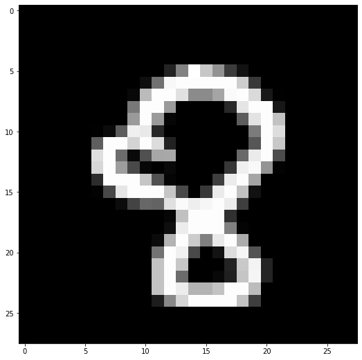
这些代码行使用 4x4 池化内核,步长为 1,遍历 112x112 2D 数组以输出 28x28 图像。

草图:
#include "num.h"
float arr1[28 * 28];
int filterWidth = 4;
int filterheight = 4;
void setup() {
  Serial.begin(9600);


}

void loop() {
  // put your main code here, to run repeatedly:
  for(int i=0; i < 28; i++){
    for(int j=0; j< 28; j++){
      int sum =0;

     for(int k =0; k<4;k++){
      for(int l =0; l<4; l++){
        sum += arr[4*(112*i+j) + 112 * k + l];
      }
     }
      sum = sum /16;
      arr1[i*28+j] = sum;
      Serial.print(sum);
     Serial.print(", ");
    }
    Serial.println("");
  }

Serial.println("");

}
9.d 探索 reshape.ipynb Colab 笔记本
本小节的 Github 链接。
代码说明:
from skimage.transform import resize
t = number28.reshape(28,28)
print(t.shape)
number112 = resize(t, (112, 112))
print(number112.dtype)
"""
for i in range(0,112):
  for j in range(0,112):
    if number112[i][j] < 10e-20:
      number112[i][j] = 0
      /
"""
for i in range(0,112):
  for j in range(0,112):
      number112[i][j] = number112[i][j] * 10e+19
      if number112[i][j] < 10:
       number112[i][j] = 0
np.amax(number112)
number112 = number112 /12
np.amax(number112)
plt.imshow(number112, cmap='gray', interpolation='none')
plt.imshow(t, cmap='gray', interpolation='none')
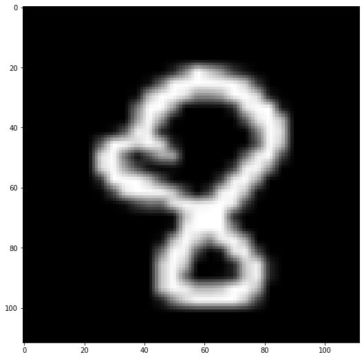
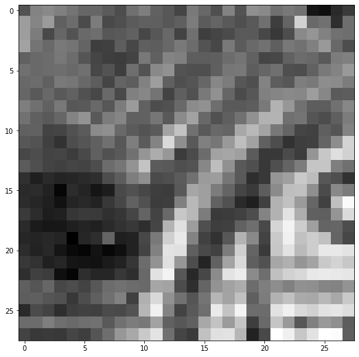
这些代码行将 28X28 MNIST 图像放大为 112X112 图像。
def matprint(mat, fmt="g"):
    col_maxes = [max([len(("{:"+fmt+"}").format(x)) for x in col]) for col in mat.T]
    for x in mat:
        for i, y in enumerate(x):
            print(("{:"+str(col_maxes[i])+fmt+"}").format(y), end=",")
        print("")
matprint(number112)
这些代码行打印放大的 112X112 MNIST 图像。
number28new = number28new.reshape(28,28)
for i in range(0,28):
  for j in range(0,28):
      if number28new[i][j] < 35:
       number28new[i][j] = 0
plt.imshow(number28new, cmap='gray', interpolation='none')
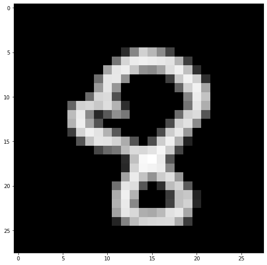
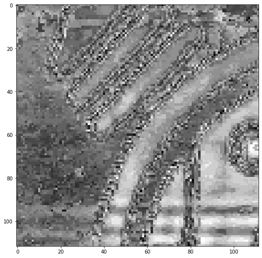
这些代码行打印重新整形的 28x28 MNIST 图像。
10. 测试 TinyML 模型
现在我们已经构建了一个 TinyML 模型并测试了将数据输入模型的两种方法,是时候将 TinyML 模型集成到主应用程序中了。
10.a TinyML 模型:输入测试
本小节的 Github 链接。
我们如何发送输入数据?
对于基于时间序列的模型,很明显发送输入数据是因为输入张量是一维数组。
//1D input tensor
tflInputTensor->data.f[i * 3 + 0] = (ax + 8.0) / 16.0;
tflInputTensor->data.f[i * 3 + 1] = (ay + 8.0) / 16.0;
tflInputTensor->data.f[i * 3 + 2] = (az + 8.0) / 16.0;
我不知道如何将数据发送到这个特定的 TinyML 模型,所以我设计了一个测试。
我将 MNIST 训练数据的数组值存储到 num.h 文件中。
数小时:
float num[784] = {0,0,0,0,0,0,  0,  0,  0,  0,  0,  0,  0,  0,  0,  0,  0,  0,  0,  0,  0,  0,0,0,0,0,0,0,
0,0,0,0,0,0,  0,  0,  0,  0,  0,  0,  0,  0,  0,  0,  0,  0,  0,  0,  0,  0,0,0,0,0,0,0,
0,0,0,0,0,0,  0,  0,  0,  0,  0,  0,  0,  0,  0,  0,  0,  0,  0,  0,  0,  0,0,0,0,0,0,0,
0,0,0,0,0,0,  0,  0,  0,  0,  0,  0,  0,  0,  0,  0,  0,  0,  0,  0,  0,  0,0,0,0,0,0,0,
0,0,0,0,0,0,  0,  0,  0,  0,  0,  0,  0,  0,  0,  0,  0,  0,  0,  0,  0,  0,0,0,0,0,0,0,
0,0,0,0,0,0,  0,  0,  0,  0,  0,  0, 49,143,223,196,149, 73,  0,  0,  0,  0,0,0,0,0,0,0,
0,0,0,0,0,0,  0,  0,  0,  0,  0,126,228,252,257,252,248,242,193, 67,  0,  0,0,0,0,0,0,0,
0,0,0,0,0,0,  0,  0,  0,  0,176,247,254,213,156,149,175,236,256,204, 53,  0,0,0,0,0,0,0,
0,0,0,0,0,0,  0,  0,  0,119,246,248,156,  0,  0,  0,  0, 69,216,259,221, 50,0,0,0,0,0,0,
0,0,0,0,0,0,  0,  0,  0,166,246,160,  0,  0,  0,  0,  0,  0,107,225,259,177,0,0,0,0,0,0,
0,0,0,0,0,0,  0,  0,115,229,234, 86,  0,  0,  0,  0,  0,  0,  0,142,252,209,0,0,0,0,0,0,
0,0,0,0,0,0,107,223,230,214,237,192, 50,  0,  0,  0,  0,  0,  0,124,245,186,0,0,0,0,0,0,
0,0,0,0,0,0,201,251,147, 44, 95,154,127,  0,  0,  0,  0,  0,116,224,235, 91,0,0,0,0,0,0,
0,0,0,0,0,0,192,254,178, 89,  0,  0,  0,  0,  0,  0,  0, 80,224,242,149,  0,0,0,0,0,0,0,
0,0,0,0,0,0, 67,227,256,244,190, 94,  0,  0,  0,  0, 82,218,248,163,  0,  0,0,0,0,0,0,0,
0,0,0,0,0,0,  0, 91,210,245,244,227,184, 90,  0, 84,219,256,188, 38,  0,  0,0,0,0,0,0,0,
0,0,0,0,0,0,  0,  0,  0, 76,114,127,201,234,231,244,263,218, 74,  0,  0,  0,0,0,0,0,0,0,
0,0,0,0,0,0,  0,  0,  0,  0,  0,  0, 47,205,266,273,250, 92,  0,  0,  0,  0,0,0,0,0,0,0,
0,0,0,0,0,0,  0,  0,  0,  0,  0,  0, 44,227,264,260,253,145,  0,  0,  0,  0,0,0,0,0,0,0,
0,0,0,0,0,0,  0,  0,  0,  0,  0,  0,173,251,208,158,218,239,163,  0,  0,  0,0,0,0,0,0,0,
0,0,0,0,0,0,  0,  0,  0,  0,  0,120,245,236, 92,  0, 52,201,227, 98,  0,  0,0,0,0,0,0,0,
0,0,0,0,0,0,  0,  0,  0,  0,  0,184,256,192,  0,  0,  0, 65,205,213, 40,  0,0,0,0,0,0,0,
0,0,0,0,0,0,  0,  0,  0,  0,  0,192,250,146,  0,  0,  0, 70,206,225, 42,  0,0,0,0,0,0,0,
0,0,0,0,0,0,  0,  0,  0,  0,  0,173,247,232,186,181,199,240,249,178,  0,  0,0,0,0,0,0,0,
0,0,0,0,0,0,  0,  0,  0,  0,  0, 39,140,201,226,230,232,233,184, 65,  0,  0,0,0,0,0,0,0,
0,0,0,0,0,0,  0,  0,  0,  0,  0,  0,  0,  0,  0,  0,  0,  0,  0,  0,  0,  0,0,0,0,0,0,0,
0,0,0,0,0,0,  0,  0,  0,  0,  0,  0,  0,  0,  0,  0,  0,  0,  0,  0,  0,  0,0,0,0,0,0,0,
0,0,0,0,0,0,  0,  0,  0,  0,  0,  0,  0,  0,  0,  0,  0,  0,  0,  0,  0,  0,0,0,0,0,0,0};
模型.h:
//MPU6050_model.ino
#include
代码说明:输入张量:
for(int i = 0; i < 28; i++){
  for(int j =0; j < 28; j++){
      tflInterpreter->input(0)->data.f[28*i+j] = num[28*i+j] / 255;
    }
  }
为了测试输入张量,我使用 2D 循环发送输入数据。
for(int i = 0; i < 28; i++){
  for(int j =0; j < 28; j++){
      Serial.print(tflInterpreter->input(0)->data.f[28*i+j]);
      Serial.print(", ");
    }
      Serial.println("");
  }
Serial.println("");
然后,我打印出存储在 TinyML 模型的输入张量中的值。
for(int i = 0; i < 28; i++){
  for(int j =0; j < 28; j++){
      Serial.print(num[28*i+j]);
      Serial.print(", ");
    }
      Serial.println("");
  }
Serial.println("");
然后我打印出存储在循环中的实际值。
for(int i = 0; i < 28; i++){
  for(int j =0; j < 28; j++){
      Serial.print(tflInterpreter->input(0)->data.f[28*i+j]-num[28*i+j]);
      Serial.print(", ");
    }
      Serial.println("");
  }
最后,我打印出存储在输入张量中的值与存储在数组中的值之间的差异。如果所有差异都为零,则输入已按照我们想要的方式正确存储在输入张量中。
10.b TinyML 模型:模型测试
本小节的 Github 链接。
现在我们已经弄清楚了如何发送输入数据,是时候测试模型了。这段代码与上面的代码相同,只是调用了推理并打印了输出张量。
num.h 文件:
float num[784] = {0,0,0,0,0,0,  0,  0,  0,  0,  0,  0,  0,  0,  0,  0,  0,  0,  0,  0,  0,  0,0,0,0,0,0,0,
0,0,0,0,0,0,  0,  0,  0,  0,  0,  0,  0,  0,  0,  0,  0,  0,  0,  0,  0,  0,0,0,0,0,0,0,
0,0,0,0,0,0,  0,  0,  0,  0,  0,  0,  0,  0,  0,  0,  0,  0,  0,  0,  0,  0,0,0,0,0,0,0,
0,0,0,0,0,0,  0,  0,  0,  0,  0,  0,  0,  0,  0,  0,  0,  0,  0,  0,  0,  0,0,0,0,0,0,0,
0,0,0,0,0,0,  0,  0,  0,  0,  0,  0,  0,  0,  0,  0,  0,  0,  0,  0,  0,  0,0,0,0,0,0,0,
0,0,0,0,0,0,  0,  0,  0,  0,  0,  0, 49,143,223,196,149, 73,  0,  0,  0,  0,0,0,0,0,0,0,
0,0,0,0,0,0,  0,  0,  0,  0,  0,126,228,252,257,252,248,242,193, 67,  0,  0,0,0,0,0,0,0,
0,0,0,0,0,0,  0,  0,  0,  0,176,247,254,213,156,149,175,236,256,204, 53,  0,0,0,0,0,0,0,
0,0,0,0,0,0,  0,  0,  0,119,246,248,156,  0,  0,  0,  0, 69,216,259,221, 50,0,0,0,0,0,0,
0,0,0,0,0,0,  0,  0,  0,166,246,160,  0,  0,  0,  0,  0,  0,107,225,259,177,0,0,0,0,0,0,
0,0,0,0,0,0,  0,  0,115,229,234, 86,  0,  0,  0,  0,  0,  0,  0,142,252,209,0,0,0,0,0,0,
0,0,0,0,0,0,107,223,230,214,237,192, 50,  0,  0,  0,  0,  0,  0,124,245,186,0,0,0,0,0,0,
0,0,0,0,0,0,201,251,147, 44, 95,154,127,  0,  0,  0,  0,  0,116,224,235, 91,0,0,0,0,0,0,
0,0,0,0,0,0,192,254,178, 89,  0,  0,  0,  0,  0,  0,  0, 80,224,242,149,  0,0,0,0,0,0,0,
0,0,0,0,0,0, 67,227,256,244,190, 94,  0,  0,  0,  0, 82,218,248,163,  0,  0,0,0,0,0,0,0,
0,0,0,0,0,0,  0, 91,210,245,244,227,184, 90,  0, 84,219,256,188, 38,  0,  0,0,0,0,0,0,0,
0,0,0,0,0,0,  0,  0,  0, 76,114,127,201,234,231,244,263,218, 74,  0,  0,  0,0,0,0,0,0,0,
0,0,0,0,0,0,  0,  0,  0,  0,  0,  0, 47,205,266,273,250, 92,  0,  0,  0,  0,0,0,0,0,0,0,
0,0,0,0,0,0,  0,  0,  0,  0,  0,  0, 44,227,264,260,253,145,  0,  0,  0,  0,0,0,0,0,0,0,
0,0,0,0,0,0,  0,  0,  0,  0,  0,  0,173,251,208,158,218,239,163,  0,  0,  0,0,0,0,0,0,0,
0,0,0,0,0,0,  0,  0,  0,  0,  0,120,245,236, 92,  0, 52,201,227, 98,  0,  0,0,0,0,0,0,0,
0,0,0,0,0,0,  0,  0,  0,  0,  0,184,256,192,  0,  0,  0, 65,205,213, 40,  0,0,0,0,0,0,0,
0,0,0,0,0,0,  0,  0,  0,  0,  0,192,250,146,  0,  0,  0, 70,206,225, 42,  0,0,0,0,0,0,0,
0,0,0,0,0,0,  0,  0,  0,  0,  0,173,247,232,186,181,199,240,249,178,  0,  0,0,0,0,0,0,0,
0,0,0,0,0,0,  0,  0,  0,  0,  0, 39,140,201,226,230,232,233,184, 65,  0,  0,0,0,0,0,0,0,
0,0,0,0,0,0,  0,  0,  0,  0,  0,  0,  0,  0,  0,  0,  0,  0,  0,  0,  0,  0,0,0,0,0,0,0,
0,0,0,0,0,0,  0,  0,  0,  0,  0,  0,  0,  0,  0,  0,  0,  0,  0,  0,  0,  0,0,0,0,0,0,0,
0,0,0,0,0,0,  0,  0,  0,  0,  0,  0,  0,  0,  0,  0,  0,  0,  0,  0,  0,  0,0,0,0,0,0,0
草图:
//MPU6050_model.ino
#include
代码说明:
TfLiteStatus invokeStatus = tflInterpreter->Invoke();
这些代码行对存储在输入张量中的数据调用推理。
out[0] = tflInterpreter->output(0)->data.f[0];
  out[1] = tflInterpreter->output(0)->data.f[1];
  out[2] = tflInterpreter->output(0)->data.f[2];
  out[3] = tflInterpreter->output(0)->data.f[3];
  out[4] = tflInterpreter->output(0)->data.f[4];
  out[5] = tflInterpreter->output(0)->data.f[5];
  out[6] = tflInterpreter->output(0)->data.f[6];
  out[7] = tflInterpreter->output(0)->data.f[7];
  out[8] = tflInterpreter->output(0)->data.f[8];
  out[9] = tflInterpreter->output(0)->data.f[9];
这些代码行访问输出张量并将它们存储在一个数组中以供以后使用。
float maxVal = out[0];
int maxIndex = 0;
for(int k =0; k < 10;k++){
  if (out[k] > maxVal) {
      maxVal = out[k];
      maxIndex = k;
    }
  }
Serial.print("Number ");
Serial.print(maxIndex);
Serial.println(" detected");
Serial.print("Confidence: ");
Serial.println(maxVal);
这几行代码打印出输出值最高的类的类索引和置信度值。
Serial.print(out[0]);
  Serial.print(",");
  Serial.print(out[1]);
  Serial.print(",");
  Serial.print(out[2]);
  Serial.print(",");
  Serial.print(out[3]);
  Serial.print(",");
  Serial.print(out[4]);
  Serial.print(",");
  Serial.print(out[5]);
  Serial.print(",");
  Serial.print(out[6]);
  Serial.print(",");
  Serial.print(out[7]);
  Serial.print(",");
  Serial.print(out[8]);
  Serial.print(",");
  Serial.println(out[9]);
这些代码行打印出每个单独类的置信度值。
10.c MNIST:测试图像
本小节的 Github 链接。
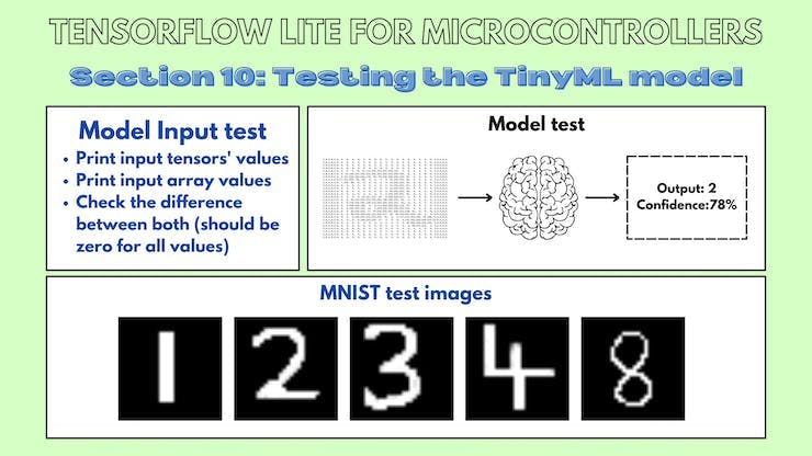
您可以使用这些转换为 NumPy 数组的图像来测试您的 MNIST TinyML 模型。

结论
我感谢我的 GSoC 导师 Paul Ruiz 在整个项目中对我的指导!
- 带有OV7670相机模块的TinyML
- 教程第4部分:带有OV7670相机模块的TinyML
- 基于OV7670的视觉捕捉系统 3次下载
- 教程第3部分:带有OV7670摄像头模块的TinyML
- (兼容正点原子引脚)OV7670 FIFO 30W摄像头介绍(一) --- 整体介绍/SCCB时序
- 基于stm32控制OV7670摄像头 133次下载
- STM32单片机移植带有FIFO摄像头的OV7670 107次下载
- 使用STM32单片机应用OV7670摄像头的AD原理图免费下载 0次下载
- OV7670的驱动程序和模块经典资料合集免费下载 53次下载
- OV7670摄像头模块的资料合集免费下载 123次下载
- OV7670模块的详细资料合集免费下载 29次下载
- 使用STM32和OV7670摄像头制作迷你相机的资料合集免费下载 36次下载
- OV7670图象传感器摄像头的调试资料和程序资料免费下载 56次下载
- OV7670使用说明和程序讲解-参考精英板 76次下载
- OV7670模块(资料总包) 211次下载
- 如何通过OV5640摄像头显示在VGA显示屏上 2997次阅读
- 微雪电子OV5640 摄像头模块B型简介 3748次阅读
- 微雪电子OV5640摄像头模块A型简介 5878次阅读
- 微雪电子OV5640 摄像头模块C型简介 2916次阅读
- 微雪电子OV7670数码摄像头模块简介 4344次阅读
- 微雪电子OV2710高清USB摄像头简介 6009次阅读
- fireflyAIO-3399J摄像头模组简介 1910次阅读
- fireflyAIO-3288C主板摄像头模组简介 2062次阅读
- FireflyRK3288的摄像头模组介绍 2256次阅读
- 关于Firefly摄像头模组的简介 3147次阅读
- 天嵌科技OV5640摄像头模块-CMOS摄像头介绍 1.2w次阅读
- 基于OmniVision的OV5640设计的USB摄像头模块 5661次阅读
- 天嵌科技OV3640摄像头模块介绍 2416次阅读
- OV7620 cmos摄像头的使用 1.1w次阅读
- 一文看懂ov7620与ov7670的区别 5.1w次阅读
下载排行
本周
- 1美的电磁炉维修手册大全
- 1.56 MB | 5次下载 | 5 积分
- 2SMD LED选型手册 贴片灯珠
- 5.47 MB | 3次下载 | 免费
- 3基于PLC的拉丝机张力控制系统研究
- 0.14 MB | 2次下载 | 5 积分
- 4LZC3106G高性能谐振控制器中文手册
- 1.29 MB | 1次下载 | 1 积分
- 5JL2233B集成电平转换功能的LDO中文手册
- 0.50 MB | 1次下载 | 免费
- 6加密芯片的一种破解方法和对应加密方案改进设计
- 0.29 MB | 1次下载 | 免费
- 7万用表UT58A原理图
- 0.09 MB | 1次下载 | 5 积分
- 8BOSCH-REXROTH300拧紧系统常见故障及处理方法
- 0.06 MB | 次下载 | 5 积分
本月
- 1使用单片机实现七人表决器的程序和仿真资料免费下载
- 2.96 MB | 44次下载 | 免费
- 2UC3842/3/4/5电源管理芯片中文手册
- 1.75 MB | 19次下载 | 免费
- 3华瑞昇CR216芯片数字万用表规格书附原理图及校正流程方法
- 0.74 MB | 14次下载 | 3 积分
- 4DMT0660数字万用表产品说明书
- 0.70 MB | 13次下载 | 免费
- 53314A函数发生器维修手册
- 16.30 MB | 13次下载 | 免费
- 6TPS54202H降压转换器评估模块用户指南
- 1.02MB | 8次下载 | 免费
- 7STM32F101x8/STM32F101xB手册
- 1.69 MB | 8次下载 | 1 积分
- 8感应笔电路图
- 0.06 MB | 7次下载 | 免费
总榜
- 1matlab软件下载入口
- 未知 | 935119次下载 | 10 积分
- 2开源硬件-PMP21529.1-4 开关降压/升压双向直流/直流转换器 PCB layout 设计
- 1.48MB | 420062次下载 | 10 积分
- 3Altium DXP2002下载入口
- 未知 | 233084次下载 | 10 积分
- 4电路仿真软件multisim 10.0免费下载
- 340992 | 191367次下载 | 10 积分
- 5十天学会AVR单片机与C语言视频教程 下载
- 158M | 183335次下载 | 10 积分
- 6labview8.5下载
- 未知 | 81581次下载 | 10 积分
- 7Keil工具MDK-Arm免费下载
- 0.02 MB | 73807次下载 | 10 积分
- 8LabVIEW 8.6下载
- 未知 | 65987次下载 | 10 积分
 电子发烧友App


 创作
创作 发文章
发文章 发帖
发帖  提问
提问  发资料
发资料 发视频
发视频 上传资料赚积分


评论