Abstract: This application note describes how to modify the pulse shape (amplitude, rise- and fall-times) of Dallas DS3150, DS315x, and DS325x Line Interface Units (LIUs).

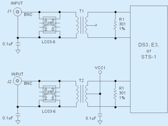
Figure 1. Original termination network.
Note 1: The connection between the center tap of the transformer and VDD should not exist for the DS315X and DS325X devices.
Figure 1 shows the original termination network for the DS3150, DS315X and DS325X. Figure 2 shows the pulse captured when the signal was terminated with a 75Ω resistor.

Figure 2. E3 pulse using the original termination network.

Figure 3. Original termination network with capacitor from TX_PLUS to GND.
Note 2: The connection between the center tap of the transformer and VDD should not exist for the DS315X and DS325X devices.
Due to double reflection, the amplitude on the left side is increased and is in the middle of the template specification.

Figure 4. E3 pulse using the 6pF capacitor to improve the amplitude with medium cable length.
Figure 4 shows that the undershoot on the left side of the pulse has changed, but there is overshoot on the right side of the pulse.
When a longer cable with 75Ω termination is used, the overshoot on the right side of the pulse disappears. The longer cable causes the capacitance to increase and the impedance to decrease, resulting in lower positive feedback. This causes the overshoot to be minimized. Figure 5 shows the effects of the longer cable, which improves the overshoot on he right side of the pulse.
The overshoot may change slightly based on the cable length used to connect the DS3150DK or the DS3154DK to the oscilloscope. For the reminder of the application note, cable is divided into three categories:

Figure 5. E3 pulse using the 6pF capacitor to improve the amplitude with long cable length.
The resistor combinations that can be used are:

Figure 6. Original termination network with resistor divider.
Note 3: The connection between the center tap of the transformer and VDD should not exist for the DS315X and DS325X devices. The capacitor should be connected to GND from the resistor divider instead of the center tap of the transformer for the DS315X and DS325X device.
The pulse's undershoot or overshoot also depends on the cable length of the termination network. Figure 7 shows the E3 pulse using the resistor divider with a 110Ω and 220Ω with a short cable. Though the amplitude of the pulse increases, we see some overshoot on the falling edge.

Figure 7. E3 pulse using the resistor divider with 110Ω and 220Ω with a short cable.
With medium cable length, the pulse shape improves over the short cable length. The overshoot at the falling edge of the pulse is also improved. Figure 8 shows the E3 pulse using the resistor divider with 110Ω and 220Ω with a medium cable length.

Figure 8. E3 pulse using the resistor divider with 110Ω and 220Ω with a medium cable length.
With a long cable length, the pulse shape is better than the medium and the short cable lengths. The overshoot at the falling edge of the pulse is no longer present. Figure 9 shows the E3 pulse using the resistor divider with 110Ω and 220Ω with a long cable length.

Figure 9. E3 pulse using the resistor divider with 110Ω and 220Ω with a long cable length.
The decision should be made based on the pulse shape that the customer obtains with their board. To improve the amplitude of the pulse, additional capacitor from TX_PLUS to GND is recommended. To have desirable distribution of the pulse, appropriate resistors may be used from TX_PLUS to VDD and TX_MINUS to VDD.
If you have further questions about the pulse shape of the DS3150 and DS315X, or the operation of the DS3150 and DS315x, please contact the Telecommunication Applications support team via email at telecom.support@dalsemi.com or call 972-371-6555.
Introduction
This application note describes how to modify the pulse shape of the following DS3/E3/STS-1 Line Interface Units (LIUs):- DS3150
- DS315X (DS3151, DS3152, DS3153 and DS3154)
- DS325X (DS3251, DS3252, DS3253 and DS3254)

Figure 1. Original termination network.
Note 1: The connection between the center tap of the transformer and VDD should not exist for the DS315X and DS325X devices.
Figure 1 shows the original termination network for the DS3150, DS315X and DS325X. Figure 2 shows the pulse captured when the signal was terminated with a 75Ω resistor.

Figure 2. E3 pulse using the original termination network.
Improving the Amplitude of the Pulse Using a Capacitor
To modify the undershoot and also increase the amplitude of the pulse, a capacitor in the range of 4.7pF to 8.0pF can be connected from TX_PLUS to GND, as Figure 3 shows.
Figure 3. Original termination network with capacitor from TX_PLUS to GND.
Note 2: The connection between the center tap of the transformer and VDD should not exist for the DS315X and DS325X devices.
Due to double reflection, the amplitude on the left side is increased and is in the middle of the template specification.

Figure 4. E3 pulse using the 6pF capacitor to improve the amplitude with medium cable length.
Figure 4 shows that the undershoot on the left side of the pulse has changed, but there is overshoot on the right side of the pulse.
When a longer cable with 75Ω termination is used, the overshoot on the right side of the pulse disappears. The longer cable causes the capacitance to increase and the impedance to decrease, resulting in lower positive feedback. This causes the overshoot to be minimized. Figure 5 shows the effects of the longer cable, which improves the overshoot on he right side of the pulse.
The overshoot may change slightly based on the cable length used to connect the DS3150DK or the DS3154DK to the oscilloscope. For the reminder of the application note, cable is divided into three categories:
| - | Short Cable Length: Cable length less than 30in. |
| - | Medium Cable Length: Cable length is more than 30in but less that 5ft. |
| - | Long Cable Length: Cable length is equal to or more than 5ft. |

Figure 5. E3 pulse using the 6pF capacitor to improve the amplitude with long cable length.
Modifying the Amplitude and the Rise/Fall Times of the Pulse Using a Resistor Divider
A resistor divider can be used to modify the undershoot, overshoot, rise time, and fall time of the pulse. Instead of the normal 330Ω from TX_PLUS to TX_MINUS, different combinations of divider resistors are used from TX_PLUS to VDD and VDD to TX_MINUS. These resistors change the distribution of the feedback loop that helps to shape the amplitude configuration.The resistor combinations that can be used are:
| - | 150Ω from TX_PLUS to VDD and 180Ω from TX_MINUS to VDD |
| - | 120Ω from TX_PLUS to VDD and 220Ω from TX_MINUS to VDD |
| - | 110Ω from TX_PLUS to VDD and 220Ω from TX_MINUS to VDD |
| - | 91Ω from TX_PLUS to VDD and 240Ω from TX_MINUS to VDD |

Figure 6. Original termination network with resistor divider.
Note 3: The connection between the center tap of the transformer and VDD should not exist for the DS315X and DS325X devices. The capacitor should be connected to GND from the resistor divider instead of the center tap of the transformer for the DS315X and DS325X device.
The pulse's undershoot or overshoot also depends on the cable length of the termination network. Figure 7 shows the E3 pulse using the resistor divider with a 110Ω and 220Ω with a short cable. Though the amplitude of the pulse increases, we see some overshoot on the falling edge.

Figure 7. E3 pulse using the resistor divider with 110Ω and 220Ω with a short cable.
With medium cable length, the pulse shape improves over the short cable length. The overshoot at the falling edge of the pulse is also improved. Figure 8 shows the E3 pulse using the resistor divider with 110Ω and 220Ω with a medium cable length.

Figure 8. E3 pulse using the resistor divider with 110Ω and 220Ω with a medium cable length.
With a long cable length, the pulse shape is better than the medium and the short cable lengths. The overshoot at the falling edge of the pulse is no longer present. Figure 9 shows the E3 pulse using the resistor divider with 110Ω and 220Ω with a long cable length.

Figure 9. E3 pulse using the resistor divider with 110Ω and 220Ω with a long cable length.
Conclusion
In the design kits for the DS3150DK and DS3154DK, a 6pF capacitor from TX_PLUS to GND with a long cable length produced the best pulse shape. Alternatively, the addition of a resistor divider 110Ω to 220Ω from TX_PLUS to VDD and TX_MINUS to VDD with a long cable length would also produce the best pulse shape.The decision should be made based on the pulse shape that the customer obtains with their board. To improve the amplitude of the pulse, additional capacitor from TX_PLUS to GND is recommended. To have desirable distribution of the pulse, appropriate resistors may be used from TX_PLUS to VDD and TX_MINUS to VDD.
If you have further questions about the pulse shape of the DS3150 and DS315X, or the operation of the DS3150 and DS315x, please contact the Telecommunication Applications support team via email at telecom.support@dalsemi.com or call 972-371-6555.
 电子发烧友App


评论