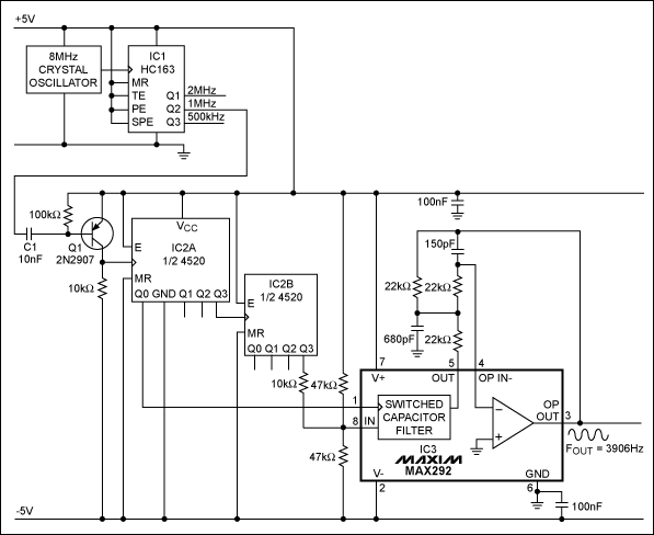
A TTL counter, an 8-channel analog multiplexer, and a 4th-order lowpass filter can generate 1kHz to 25kHz sine waves with a THD better than -80dB (Figure 1). The circuit cascades the two 2nd-order, continuous-time Sallen-Key filters within IC3 to implement the 4th-order lowpass filter. Two resistive dividers connected from ground to VDD and ground to VSS provide bipolar dc input to the multiplexer.

Figure 1. This circuit produces a pure, -80dB THD sine wave whose frequency equals fC of the IC3 filter.
To operate the circuit, you must first choose the filter's cutoff frequency, fC, by tying IC3's D0 through D6 inputs to 5V or ground. The cutoff frequency can be at 128 possible levels between 1kHz and 25kHz depending on those seven digital input levels. Because Figure 1 ties D0 through D6 to ground, fC equals 1kHz. The 100kΩ potentiometer adjusts the output leve between VDD -1.5V and VSS +1.5V.
The clock's input frequency must be eight times higher than the filter's fC. The multiplexer then produces and eight-times oversampled staircase approximation of a sine wave. Eight-times oversampling greatly simplifies the smoothing requirements of the lowpass filter by pushing the first significant harmonic out to seven times the fundamental. All higher-order harmonics are removed by IC3, which includes an uncommitted amplifier for setting the output level.
The frequency domain offers a view of filter's operation. Smaller harmonics in the multiplexer's output spectrum (Figure 2a), caused by inaccuracies in the voltage dividers, are significant with respect to the larger-amplitude harmonics associated with the staircase approximation. In the filtered output (Figure 2b), all harmomnics are lost in the noise floor of the spectrum analyzer.

Figure 2. The circuit's approximation process generates large harmonics in the multiplexer's output spectum (a), which the filter attenuates to a level below the spectrum analyzer's noise floor (b).

Figure 1. This circuit produces a pure, -80dB THD sine wave whose frequency equals fC of the IC3 filter.
To operate the circuit, you must first choose the filter's cutoff frequency, fC, by tying IC3's D0 through D6 inputs to 5V or ground. The cutoff frequency can be at 128 possible levels between 1kHz and 25kHz depending on those seven digital input levels. Because Figure 1 ties D0 through D6 to ground, fC equals 1kHz. The 100kΩ potentiometer adjusts the output leve between VDD -1.5V and VSS +1.5V.
The clock's input frequency must be eight times higher than the filter's fC. The multiplexer then produces and eight-times oversampled staircase approximation of a sine wave. Eight-times oversampling greatly simplifies the smoothing requirements of the lowpass filter by pushing the first significant harmonic out to seven times the fundamental. All higher-order harmonics are removed by IC3, which includes an uncommitted amplifier for setting the output level.
The frequency domain offers a view of filter's operation. Smaller harmonics in the multiplexer's output spectrum (Figure 2a), caused by inaccuracies in the voltage dividers, are significant with respect to the larger-amplitude harmonics associated with the staircase approximation. In the filtered output (Figure 2b), all harmomnics are lost in the noise floor of the spectrum analyzer.

Figure 2. The circuit's approximation process generates large harmonics in the multiplexer's output spectum (a), which the filter attenuates to a level below the spectrum analyzer's noise floor (b).
 电子发烧友App




评论