摘要:多种原因会促使我们把以前使用高速微控制器(DS80C310/DS80C320/DS80C323/DS8xC520)的8051设计升级到新的超高速闪存微控制器(DS89C430/DS89C450)。促使产品升级的原因是:更高的性能、增值服务和外设以及灵活的内部闪存存储器。本应用笔记讨论了两个微控制器系列的重要差异,说明如何从高速升级到超高速器件。
通过同样的方式,超高速闪存微控制器可以替换高速微控制器设计进行升级。这些功能更强大的新型微控制器包括DS89C430/DS89C450,重要改进包括:扩展了内部程序闪存存储器(达到64kB),重新设计的超高速微控制器核工作在单时钟周期指令,速度是早期8051设计的12倍。
本应用笔记讨论如何从高速微控制器升级到超高速闪存器件,介绍在升级设计时必须考虑的函数集、引脚的变动以及SFR的差异。
表4. SFR功能区别
从DS80C310/DS80C320/DS80C323向DS89C430/DS89C450移植时,存储在外部ROM、闪存或EPROM存储器的应用程序可以重新放置到超高速处理器的内部闪存。DS89C430提供与DS89xC520相同的内部程序存储器(16kB),存储在DS8xC520中的所有应用程序都可以放入DS89C430,无需调整。对于外部程序存储器的应用,可以将程序装载到DS89C450的64kB内部闪存,只要没有占用端口扩展64kB的程序存储空间。
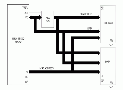
最后,由于DS89C430/DS89C450支持标准的8051复用地址总线,必要时,还可以使用外部程序存储器。
DS89C430/DS89C450增加了串口装载器,从而改进了编程过程。该功能容许程序存储器通过一个简单的基于ASCII的协议重新装载程序。串口装载器利用微控制器内部ROM实现,不会占用程序空间。另外,FCNTL和FDATA寄存器可以用于IAP,部分闪存可以在用户控制下进行擦除和重写。
但是,与P2和P3口不同,P0口采用漏极开路输出驱动器。这意味着如果这些端口被用作输出,它们必须接上拉电阻。如果P0口用作输入(由外部驱动),则不需要上拉电阻。
概述
Maxim的高速微控制器系列包括多种不同的8051微控制器,与早期的8051每机器周期12个时钟相比,它们可以达到每机器周期4个时钟的更高速度。有些高速微控制器完全利用外部程序存储器,比如DS80C310;有些控制器包含内部EPROM或ROM程序存储器,比如DS87C520/DS83C520。这些高速器件都与现有的8051微控制器引脚兼容,所以在大部分情况下,更换一个快速器件并做很少的软件调整,就可以很容易升级设计。通过同样的方式,超高速闪存微控制器可以替换高速微控制器设计进行升级。这些功能更强大的新型微控制器包括DS89C430/DS89C450,重要改进包括:扩展了内部程序闪存存储器(达到64kB),重新设计的超高速微控制器核工作在单时钟周期指令,速度是早期8051设计的12倍。
本应用笔记讨论如何从高速微控制器升级到超高速闪存器件,介绍在升级设计时必须考虑的函数集、引脚的变动以及SFR的差异。
通用参考文献
下列器件的编程指南可以参考高速微控制器用户指南(PDF,English only)。- DS80C310高速微控制器
- DS80C320高速低功耗微控制器
- DS80C323高速低功耗微控制器
- DS83C520高速ROM微控制器
- DS87C520高速EPROM微控制器
- DS89C430超高速闪存微控制器
- DS89C450超高速闪存微控制器
器件的基本功能
表1. 器件功能比较| Feature | DS80C310 | DS80C320 DS80C323 |
DS87C520 DS83C520 |
DS89C430 DS89C450 |
| Clocks per Machine Cycle | 4 | 4 | 4 | 1 |
| Operating Voltage Range (V) | 4.5 to 5.5 | 4.25 to 5.5 (DS80C320) 2.7 to 5.5 (DS80C323) |
4.5 to 5.5 | 4.5 to 5.5 |
| Clock Rate (MHz, max) | 33 | 33 (DS80C320) 18 (DS80C323) |
33 | 33 |
| Instruction Execution Time (ns, min) | 121 | 121 (DS80C320) 222 (DS80C323) |
121 | 30 |
| Crystal Multiplier | √ (x2 or x4) | |||
| Ring Oscillator | √ | √ | √ | |
| Internal Program Memory | None | None | 16kB | 16kB (DS89C430) 64kB (DS89C450) |
| Internal Register Memory (Bytes) | 256 | 256 | 256 | 256 |
| Internal MOVX Memory | None | None | 1kB | 1kB |
| Serial Ports (UARTs) | 1 | 2 | 2 | 2 |
| External Interrupts | 6 | 6 | 6 | 6 |
| Port Pins (with Bus Active) | 16 | 16 | 16 | 16 |
| Port Pins (max) | 16 | 16 | 32 | 32 |
| Timer/Counters | Three/16-bit | Three/16-bit | Three/16-bit | Three/16-bit |
| Watchdog | √ | √ | √ | |
| Dual Data Pointers | √ | √ | √ | √ |
| Autoincrement/Decrement | √ | |||
| Stop Mode | √ | √ | √ | √ |
| Power-On Reset | √ | √ | √ | √ |
| Power-Fail Interrupt | √ | √ | √ |
器件引脚排列
表2. 器件引脚的差异| DIP | PLCC | TQFP | DS80C310 | DS80C320 DS80C323 |
DS87C520 DS83C520 |
DS89C430 DS89C450 |
| 1 | 2 | 40 | P1.0 (T2) | P1.0 (T2) | P1.0 (T2) | P1.0 (T2) |
| 2 | 3 | 41 | P1.1 (T2EX) | P1.1 (T2EX) | P1.1 (T2EX) | P1.1 (T2EX) |
| 3 | 4 | 42 | P1.2 | P1.2 (RXD1) | P1.2 (RXD1) | P1.2 (RXD1) |
| 4 | 5 | 43 | P1.3 | P1.3 (TXD1) | P1.3 (TXD1) | P1.3 (TXD1) |
| 5 | 6 | 44 | P1.4 (INT2) | P1.4 (INT2) | P1.4 (INT2) | P1.4 (INT2) |
| 6 | 7 | 1 | P1.5 (nINT3) | P1.5 (nINT3) | P1.5 (nINT3) | P1.5 (nINT3) |
| 7 | 8 | 2 | P1.6 (INT4) | P1.6 (INT4) | P1.6 (INT4) | P1.6 (INT4) |
| 8 | 9 | 3 | P1.7 (nINT5) | P1.7 (nINT5) | P1.7 (nINT5) | P1.7 (nINT5) |
| 9 | 10 | 4 | RST | RST | RST | RST |
| 10 | 11 | 5 | P3.0 (RXD0) | P3.0 (RXD0) | P3.0 (RXD0) | P3.0 (RXD0) |
| 11 | 13 | 7 | P3.1 (TXD0) | P3.1 (TXD0) | P3.1 (TXD0) | P3.1 (TXD0) |
| 12 | 14 | 8 | P3.2 (nINT0) | P3.2 (nINT0) | P3.2 (nINT0) | P3.2 (nINT0) |
| 13 | 15 | 9 | P3.3 (nINT1) | P3.3 (nINT1) | P3.3 (nINT1) | P3.3 (nINT1) |
| 14 | 16 | 10 | P3.4 (T0) | P3.4 (T0) | P3.4 (T0) | P3.4 (T0) |
| 15 | 17 | 11 | P3.5 (T1) | P3.5 (T1) | P3.5 (T1) | P3.5 (T1) |
| 16 | 18 | 12 | P3.6 (nWR) | P3.6 (nWR) | P3.6 (nWR) | P3.6 (nWR) |
| 17 | 19 | 13 | P3.7 (nRD) | P3.7 (nRD) | P3.7 (nRD) | P3.7 (nRD) |
| 18 | 20 | 14 | XTAL2 | XTAL2 | XTAL2 | XTAL2 |
| 19 | 21 | 15 | XTAL1 | XTAL1 | XTAL1 | XTAL1 |
| 20 | 22, 23 | 16, 17 | GND | GND | GND | GND |
| – | 1 | 39 | GND | N/C (can be connected to GND if desired) | GND | GND |
| 21 | 24 | 18 | A8 (P2.0) | A8 (P2.0) | A8 (P2.0) | A8 (P2.0) |
| 22 | 25 | 19 | A9 (P2.1) | A9 (P2.1) | A9 (P2.1) | A9 (P2.1) |
| 23 | 26 | 20 | A10 (P2.2) | A10 (P2.2) | A10 (P2.2) | A10 (P2.2) |
| 24 | 27 | 21 | A11 (P2.3) | A11 (P2.3) | A11 (P2.3) | A11 (P2.3) |
| 25 | 28 | 22 | A12 (P2.4) | A12 (P2.4) | A12 (P2.4) | A12 (P2.4) |
| 26 | 29 | 23 | A13 (P2.5) | A13 (P2.5) | A13 (P2.5) | A13 (P2.5) |
| 27 | 30 | 24 | A14 (P2.6) | A14 (P2.6) | A14 (P2.6) | A14 (P2.6) |
| 28 | 31 | 25 | A15 (P2.7) | A15 (P2.7) | A15 (P2.7) | A15 (P2.7) |
| 29 | 32 | 26 | nPSEN | nPSEN | nPSEN | nPSEN |
| 30 | 33 | 27 | ALE | ALE | ALE | ALE/nPROG |
| 31 | 35 | 29 | nEA | nEA | nEA | nEA |
| 32 | 36 | 30 | AD7 | AD7 | AD7 (P0.7) | AD7 (P0.7) |
| 33 | 37 | 31 | AD6 | AD6 | AD6 (P0.6) | AD6 (P0.6) |
| 34 | 38 | 32 | AD5 | AD5 | AD5 (P0.5) | AD5 (P0.5) |
| 35 | 39 | 33 | AD4 | AD4 | AD4 (P0.4) | AD4 (P0.4) |
| 36 | 40 | 34 | AD3 | AD3 | AD3 (P0.3) | AD3 (P0.3) |
| 37 | 41 | 35 | AD2 | AD2 | AD2 (P0.2) | AD2 (P0.2) |
| 38 | 42 | 36 | AD1 | AD1 | AD1 (P0.1) | AD1 (P0.1) |
| 39 | 43 | 37 | AD0 | AD0 | AD0 (P0.0) | AD0 (P0.0) |
| 40 | 44 | 38 | VCC (+5V) | VCC +5V (DS80C320) VCC +3V (DS80C323) |
VCC (+5V) | VCC (+5V) |
| – | 12 | 6 | N/C | N/C | N/C | VCC (+5V) |
| – | 34 | 28 | N/C | N/C | N/C | GND |
器件寄存器
表3. SFR映射比较| Address | DS80C310 | DS80C320 DS80C323 |
DS87C520 DS83C520 |
DS89C430 DS89C450 |
| 80h | – | – | P0 | P0 |
| 81h | SP | SP | SP | SP |
| 82h | DPL | DPL | DPL | DPL |
| 83h | DPH | DPH | DPH | DPH |
| 84h | DPL1 | DPL1 | DPL1 | DPL1 |
| 85h | DPH1 | DPH1 | DPH1 | DPH1 |
| 86h | DPS | DPS | DPS | DPS |
| 87h | PCON | PCON | PCON | PCON |
| 88h | TCON | TCON | TCON | TCON |
| 89h | TMOD | TMOD | TMOD | TMOD |
| 8Ah | TL0 | TL0 | TL0 | TL0 |
| 8Bh | TL1 | TL1 | TL1 | TL1 |
| 8Ch | TH0 | TH0 | TH0 | TH0 |
| 8Dh | TH1 | TH1 | TH1 | TH1 |
| 8Eh | CKCON | CKCON | CKCON | CKCON |
| 90h | P1 | P1 | P1 | P1 |
| 91h | EXIF | EXIF | EXIF | EXIF |
| 96h | – | – | – | CKMOD |
| 98h | SCON | SCON0 | SCON0 | SCON0 |
| 99h | SBUF | SBUF0 | SBUF0 | SBUF0 |
| 9Dh | – | – | – | ACON |
| A0h | P2 | P2 | P2 | P2 |
| A8h | IE | IE | IE | IE |
| A9h | SADDR0 | SADDR0 | SADDR0 | SADDR0 |
| AAh | – | SADDR1 | SADDR1 | SADDR1 |
| B0h | P3 | P3 | P3 | P3 |
| B1h | – | – | – | IP1 |
| B8h | IP | IP | IP | IP0 |
| B9h | SADEN0 | SADEN0 | SADEN0 | SADEN0 |
| BAh | – | SADEN1 | SADEN1 | SADEN1 |
| C0h | – | SCON1 | SCON1 | SCON1 |
| C1h | – | SBUF1 | SBUF1 | SBUF1 |
| C2h | – | – | ROMSIZE | ROMSIZE |
| C4h | – | – | PMR | PMR |
| C5h | STATUS | STATUS | STATUS | STATUS |
| C7h | – | TA | TA | TA |
| C8h | T2CON | T2CON | T2CON | T2CON |
| C9h | T2MOD | T2MOD | T2MOD | T2MOD |
| CAh | RCAP2L | RCAP2L | RCAP2L | RCAP2L |
| CBh | RCAP2H | RCAP2H | RCAP2H | RCAP2H |
| CCh | TL2 | TL2 | TL2 | TL2 |
| CDh | TH2 | TH2 | TH2 | TH2 |
| D0h | PSW | PSW | PSW | PSW |
| D5h | – | – | – | FCNTL |
| D6h | – | – | – | FDATA |
| D8h | WDCON | WDCON | WDCON | WDCON |
| E0h | ACC | ACC | ACC | ACC |
| E8h | EIE | EIE | EIE | EIE |
| F0h | B | B | B | B |
| F1h | – | – | – | EIP1 |
| F8h | EIP | EIP | EIP | EIP0 |
表4. SFR功能区别
| SFR | Bit(s) | Differences |
| P0 | – | DS8xC520/DS89C430/DS89C450 only; controls Port 0 pins. |
| DPS | 4 (AID) | DS89C430/DS89C450 only; controls the autoincrement/decrement function for the active data pointer. |
| 5 (TSL) | DS89C430/DS89C450 only; enables automatic toggling between data pointers after certain opcodes. | |
| 6 (ID0) | DS89C430/DS89C450 only; controls the effect of INC DPTR (increment or decrement) on DPTR. | |
| 7 (ID1) | DS89C430/DS89C450 only; controls the effect of INC DPTR (increment or decrement) on DPTR1. | |
| PCON | 4 (OFDE) | DS89C430/DS89C450 only; crystal oscillator fail detection enable. |
| 5 (OFDF) | DS89C430/DS89C450 only; crystal oscillator fail detection flag. | |
| CKCON | 7 (WD1) 6 (WD0) |
On all devices except the DS80C310; these bits control the watchdog timer period. |
| EXIF | 0 (BGS) | On all devices except the DS80C310; this bit enables/disables the bandgap reference during stop mode. |
| 1 (RGSL) | On all devices except the DS80C310; this bit controls execution from the ring oscillator during the crystal warmup period. | |
| 2 (RGMD) | On all devices except the DS80C310; this flag indicates the current clock source (ring or crystal). | |
| 3 | DS8xC520 (XT/nRG); selects the ring oscillator or crystal as the desired clock source. DS89C430/DS89C450 (CKRY); indicates that the crystal oscillator or crystal multiplier has completed its warmup period. | |
| CKMOD | 3 (T0MH) | DS89C430/DS89C450 only; allows Timer 0 to run directly from the system clock (clock/1). |
| 4 (T1MH) | DS89C430/DS89C450 only; allows Timer 1 to run directly from the system clock (clock/1). | |
| 5 (T2MH) | DS89C430/DS89C450 only; allows Timer 2 to run directly from the system clock (clock/1). | |
| ACON | 5 (PAGES0) 6 (PAGES1) |
DS89C430/DS89C450 only; selects the page-mode configuration for external bus operations. |
| 7 (PAGEE) | DS89C430/DS89C450 only; enables page mode (as opposed to the standard 8051 expanded bus mode) for external bus operations. | |
| IE | 6 (ES1) | On all devices except the DS80C310; this bit enables/disables the serial port 1 interrupt. |
| SADDR1 | – | On all devices except the DS80C310; this register controls the slave address for serial port 1. |
| IP1 | – | DS89C430/DS89C450 only; this register combines with the settings in IP0/IP to provide four priority-level settings for each interrupt (as opposed to two settings with IP only). |
| SADEN1 | – | On all devices except the DS80C310; this register sets the slave address mask for serial port 1. |
| SCON1 | – | On all devices except the DS80C310; this register controls mode settings for serial port 1. |
| SBUF1 | – | On all devices except the DS80C310; this register provides the input/output buffer for serial port 1. |
| ROMSIZE | 2:0 (RMS2:0) | DS8xC520/DS89C430/DS89C450 only; selects the range of on-chip EPROM/flash that maps into program space. |
| 3 (PRAME) | DS89C430/DS89C450 only; enables/disables mapping of the 1kB internal RAM into program space. | |
| PMR | 1:0 (DME1:0) | DS8xC520/DS89C430/DS89C450 only; controls mapping of internal data memory into data space. |
| 2 | DS8xC520 (ALEOFF); when set to 1, disables ALE during on-board memory access. DS89C430/DS89C450 (ALEON); when set to 0, disables ALE during on-board memory access. | |
| 3 | DS8xC520 (XTOFF); when set to 1, disables the crystal oscillator (must run from ring). DS89C430/DS89C450 (4X/n2X); sets the mode for the crystal multiplier. | |
| 4 (CTM) | DS89C430/DS89C450 only; when set to 1, enables the crystal multiplier. | |
| 5 (SWB) | DS8xC520/DS89C430/DS89C450 only; when set to 1, enables automatic switchback mode. | |
| 7:6 (CD1:0) | DS8xC520/DS89C430/DS89C450 only; controls the clock division or multiplier mode. Note that the available settings are different on the DS8xC520/DS89C430/DS89C450. | |
| STATUS | 0 (SPRA0) | DS8xC520/DS89C430/DS89C450 only; indicates that a character is currently being received on serial port 0. |
| 1 (SPTA0) | DS8xC520/DS9C430/DS89C450 only; indicates that a character is currently being transmitted on serial port 0. | |
| 2 (SPRA1) | DS8xC520/DS89C430/DS89C450 only; indicates that a character is currently being received on serial port 1. | |
| 3 (SPTA0) | DS8xC520/DS89C430/DS89C450 only; indicates that a character is currently being transmitted on serial port 1. | |
| 4 (XTUP) | DS8xC520 only; indicates whether the crystal oscillator has completed its warmup cycle. | |
| 5 (LIP) | DS80C320/DS80C323/DS8xC520 only; indicates that a low-priority interrupt is currently being serviced. | |
| 6 (HIP) | DS80C320/DS80C323/DS8xC520 only; indicates that a high-priority interrupt is currently being serviced. | |
| 7 (PIP) | DS80C320/DS80C323/DS8xC520 only; indicates that a power-fail priority interrupt is currently being serviced. | |
| 7:5 (PIS2:0) | DS89C430/DS89C450 only; indicates that the priority level of the interrupt is being serviced. | |
| TA | – | On all except the DS80C310; controls the Timed Access register protection mechanism. |
| WDCON | 0 (RWT) | On all devices except the DS80C310; resets the watchdog timer. |
| 1 (EWT) | On all devices except the DS80C310; enables/disables the watchdog timer. | |
| 2 (WTRF) | On all devices except the DS80C310; indicates that a watchdog timer reset has occurred. | |
| 3 (WDIF) | On all devices except the DS80C310; indicates that a watchdog timer interrupt has occurred. | |
| 4 (PFI) | On all devices except the DS80C310; indicates that a power-fail interrupt has occurred. | |
| 5 (EPFI) | On all devices except the DS80C310; enables/disables the power-fail interrupt. | |
| 6 (POR) | On all devices; indicates that a power-on reset has occurred. | |
| 7 (SMOD_1) | On all devices except the DS80C310; enables/disables baud-rate doubling mode for serial port 1. | |
| EIE | 4 (EWDI) | On all devices except the DS80C310; enables/disables interrupts from the watchdog timer. |
| EIP | 3:0 (PX5:2) | On all devices except the DS89C430/DS89C450; sets high/low priority for external interrupts 2, 3, 4, and 5. |
| 4 (PWDI) | DS80C320/DS80C323/DS8xC520 only; sets high/low priority for the watchdog timer interrupt. | |
| EIP1, EIP0 | – | DS89C430/DS89C450 only; these registers set priority levels 0–3 for the watchdog timer interrupt and external interrupts 2, 3, 4, and 5. |
单周期指令
超高速DS89C430/DS89C450处理器工作在单周期指令,执行一条指令只需一个时钟周期,DS80C310/DS80C320/DS80C323/DS8xC520高速处理器需要四个时钟周期完成一个机器周期,相比之下速度提高4倍。时钟速度的不同意味着相同晶体频率下,用DS89C430/DS89C450替代高速器件就将速度提升4倍。非易失存储器
DS80C310/DS80C320/DS80C323没有内部程序存储器,需要外部存储器存储程序。DS8xC520改进了存储器方案,包含16kB的程序EPROM。从DS80C310/DS80C320/DS80C323向DS89C430/DS89C450移植时,存储在外部ROM、闪存或EPROM存储器的应用程序可以重新放置到超高速处理器的内部闪存。DS89C430提供与DS89xC520相同的内部程序存储器(16kB),存储在DS8xC520中的所有应用程序都可以放入DS89C430,无需调整。对于外部程序存储器的应用,可以将程序装载到DS89C450的64kB内部闪存,只要没有占用端口扩展64kB的程序存储空间。
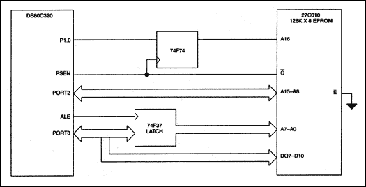
最后,由于DS89C430/DS89C450支持标准的8051复用地址总线,必要时,还可以使用外部程序存储器。
串口装载器
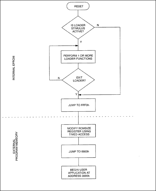
虽然DS8xC520包含内部EPROM程序存储器,但不支持在系统或在应用编程(IAP)。必须用独立的编程器装载EPROM,而且DS8xC520重新编程时必须断开(或电气隔离)与系统其它电路的连接(但是,有可能在DS8xC520上设计一个用户装载器,以允许外部程序或数据EPROM或非易失RAM在系统控制下重新加载。更多信息请参考应用笔记102,"Using the High-Speed Microcontroller as a Bootstrap Loader")。DS89C430/DS89C450增加了串口装载器,从而改进了编程过程。该功能容许程序存储器通过一个简单的基于ASCII的协议重新装载程序。串口装载器利用微控制器内部ROM实现,不会占用程序空间。另外,FCNTL和FDATA寄存器可以用于IAP,部分闪存可以在用户控制下进行擦除和重写。
GPIO端口0
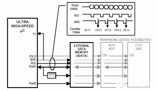
由于DS89C430/DS89C450 (类似于DS8xC520)可以在没有外部程序和数据存储器的情况下工作,所以它们的8个P0口(复用总线有效时作为AD[7:0])可以用作通用I/O (GPIO)。不使用外部总线时,还有一些I/O引脚可以重新定义为通用I/O:8个P2口(P2[7:0])、P3.6 (nWR)和P3.7 (nRD)引脚。但是,与P2和P3口不同,P0口采用漏极开路输出驱动器。这意味着如果这些端口被用作输出,它们必须接上拉电阻。如果P0口用作输入(由外部驱动),则不需要上拉电阻。
 电子发烧友App







评论