Abstract: A general-purpose current-measurement system employs a current transformer, ac-coupled to a transimpedance amplifier.
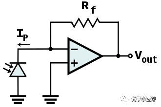
Transimpedance amplifiers are a good method for converting current to voltage in most current-measurement applications. The current source feeds into the virtual ground of an op amp, and the transimpedance can be adjusted by changing the value of a single resistor (Figure 1). As another benefit of this arrangement, the circuit gain for input offset voltage is no greater than unity.

Figure 1. For resistor values less than 20MΩ, this simple transimpedance amplifier is acceptable for use with some current sources.
Resistor values above 20MΩ are notoriously difficult to apply. For applications requiring a transimpedance above 20MΩ, consider the circuit of Figure 2. The output voltage-divider adds voltage gain that multiplies the transimpedance value, enabling effective transimpedances greater than 200MΩ. Note that the gain for input offset voltage now equals the additional voltage gain.

Figure 2. Additional voltage gain in this circuit (vs. that of Figure 1) provides effective transimpedances greater than 200MΩ.
These forms of the transimpedance amplifier are useful for inputs that closely resemble an ideal current source, like, for example, a photo-diode preamplifier. These forms, however, are not suitable for use with a current transformer. A current transformer is similar to an ideal current source, but its source impedance goes to zero at DC. (True current sources exhibit infinite impedance at all frequencies.)
The virtual ground (summing node) at the op amp's inverting input is not at zero potential, but at a potential equal to the op amp's input offset voltage. Thus, connecting a current transformer to the input shorts that summing node directly to ground, causing the output (VOUT) to equal the input offset multiplied by the amplifier's open-loop gain. The output thus saturates in the positive or negative direction, rendering that approach useless.
The circuit of Figure 3 overcomes this problem by AC-coupling the current transformer to the transimpedance amplifier. Note that the capacitor value required depends on the application; capacitor value affects the low-frequency response, and by resonating with the transfomer inductance, it can produce output peaks at higher frequencies. Settling time, which depends on the values of R1 and C1, can be as much as one second. That behavior can be a problem in systems for which the amplifier is turned on for short periods only.

Figure 3. AC-coupling enables this circuit to tolerate the zero source impedance (at DC) of a current-transformer input.
The selection of amplifier in Figure 3 depends on the application, but it generally requires wide bandwidth, low input offset, and low-power operation.
This design idea (#597) appeared in the May '04 issue of Selezione (Italy).
About transimpedance and transconductance: The words "transconductance" and "transimpedance" are often used interchangeably. Technically, the terms differ: a transimpedance amp delivers an output voltage that is a function of the input current; conversely, a transconductance amp converts a voltage to a current.Current transformers are not only a convenient means for current measurement in many applications, but also provide isolation while absorbing very little power from the source. The output current from a current transformer can be converted to voltage with a suitably valued resistor, but that approach can dramatically reduce the transformer's high-frequency response.
Transimpedance amplifiers are a good method for converting current to voltage in most current-measurement applications. The current source feeds into the virtual ground of an op amp, and the transimpedance can be adjusted by changing the value of a single resistor (Figure 1). As another benefit of this arrangement, the circuit gain for input offset voltage is no greater than unity.

Figure 1. For resistor values less than 20MΩ, this simple transimpedance amplifier is acceptable for use with some current sources.
Resistor values above 20MΩ are notoriously difficult to apply. For applications requiring a transimpedance above 20MΩ, consider the circuit of Figure 2. The output voltage-divider adds voltage gain that multiplies the transimpedance value, enabling effective transimpedances greater than 200MΩ. Note that the gain for input offset voltage now equals the additional voltage gain.

Figure 2. Additional voltage gain in this circuit (vs. that of Figure 1) provides effective transimpedances greater than 200MΩ.
These forms of the transimpedance amplifier are useful for inputs that closely resemble an ideal current source, like, for example, a photo-diode preamplifier. These forms, however, are not suitable for use with a current transformer. A current transformer is similar to an ideal current source, but its source impedance goes to zero at DC. (True current sources exhibit infinite impedance at all frequencies.)
The virtual ground (summing node) at the op amp's inverting input is not at zero potential, but at a potential equal to the op amp's input offset voltage. Thus, connecting a current transformer to the input shorts that summing node directly to ground, causing the output (VOUT) to equal the input offset multiplied by the amplifier's open-loop gain. The output thus saturates in the positive or negative direction, rendering that approach useless.
The circuit of Figure 3 overcomes this problem by AC-coupling the current transformer to the transimpedance amplifier. Note that the capacitor value required depends on the application; capacitor value affects the low-frequency response, and by resonating with the transfomer inductance, it can produce output peaks at higher frequencies. Settling time, which depends on the values of R1 and C1, can be as much as one second. That behavior can be a problem in systems for which the amplifier is turned on for short periods only.

Figure 3. AC-coupling enables this circuit to tolerate the zero source impedance (at DC) of a current-transformer input.
The selection of amplifier in Figure 3 depends on the application, but it generally requires wide bandwidth, low input offset, and low-power operation.
This design idea (#597) appeared in the May '04 issue of Selezione (Italy).
 电子发烧友App










评论