Abstract: Applying a unique 3-channel RS-485 transceiver displaying many unusual features increases reliability and fault-detection in motor-control applications. Designed specifically for motor shaft encoder applications, the MAX3097 and MAX3098 feature three differential channels to handle optical encoder data, ±15kV ESD protection, increased common mode rejection to -10 and +13.2V, three separate fault-alarm flags, and fail safe open and short detection. Alarm flags indicate open or shorted line conditions, excessive common-mode voltage range, and low-signal strength.
Modern factories use large electric motors to control machines that are necessary for the operation of the plant. For increased flexibility and accuracy, these electric motors are sometimes processor-controlled. It is imperative that the electronics controlling these large motors are designed in such a way that, if a problem occurs, the motor is safely and quickly shut down. Failure to detect a problem and to sufficiently control the motor can result in the destruction of expensive equipment, as well as in injury or possibly even death. The MAX3097E/MAX3098E were specifically designed to be used with motors in absolute positioning control loops. These parts have unique features which enable a safer and more robust design in harsh industrial environments. To better understand the unique features of the MAX3097E/MAX3098E, let's first review the basics of motor control.

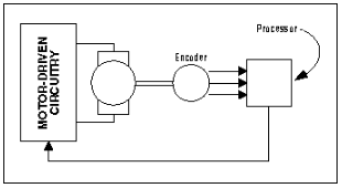
Figure 1. The major building blocks of processor-controlled electric motors.
The blocks in Figure 1 include a processor, motor-drive circuitry, an electric motor, and an encoder. The processor decides how hard and where the motor should be driven. The motor-drive circuitry contains all the necessary power electronics to drive the motor and the encoder provides position, direction, and velocity information to the processor, thus closing the loop. To understand the operation of the MAX3097E/MAX3098E, it is necessary to have a good grasp of the operation of the encoder.

Figure 2. Optical encoder disk.

Figure 3. A typical remote installation of a motor encoder.
This solution is significantly more robust than a system not using RS-485 drivers. However, there are problems that occur with long line lengths, which the MAX3097E/MAX3098E are specifically designed to address, improving on 26LS31 and 26LS32 type devices in the following ways:

Figure 4. MAX3097 pinout.
The AlarmA, AlarmB, and AlarmZ all function identically, but indicate faults on their respective wires. The Fault-D output is an OR of the three signals. In addition, it has a programmable delay built in. This output should be used for global alarm. The delay is there to stop a false triggering of the fault detectors when signals are crossing over each other. The errors that can be detected and how the MAX3097E/MAX3098E can be used to determine which errors have occurred are described below.

Figure 5. This shows the fault alarm on channel A due to the excessive common-mode range; the fault indicates that the data during this period can be unreliable.
Typically, a receiver connection contains a terminating resistor to dampen reflections, as shown in Figure 6. Usual values are either 100Ω or 120Ω, depending on the impedance of the connecting cable used.

Figure 6. Receiver input connection.
Figure 6 shows the connection of the receiver of the motor encoder signals. Because of the terminating resistor's presence, if A\ is suddenly disconnected then the voltage level of A\ would be pulled toward the voltage level at A. In the MAX3097E, there is a threshold comparator that trips the fault output if | VA-A\ | < 400mV. This technique allows the part to detect if there is an open circuit on one of the lines. For this technique to work, the terminating resistor must be present. Therefore, a terminating resistor should be placed on the same board as the receiver, rather than being connected across external screw terminals where there is a chance it could fall off.
During normal transitions, there is a crossover time for signals A and A\. This would trip the fault comparator, as |VA-A\| < 400mV. To avoid spurious signals, the global fault output (Fault D) should be used. The MAX3097E/MAX3098E include a fault-blanking feature on Fault D that makes sure that the output doesn't toggle until the fault has been present for a fixed period of time (user-settable with an external capacitor). This ensures that the motor controller isn't unnecessarily interrupted for spurious crossover signals.
This situation is very similar to the one with the open circuit, in that if A and A\ are shorted together the voltage differential will be less than 400mV, thus the fault output.

Figure 7. Detecting shorts between differential signals.

Figure 8. Detecting poor signal strength.
Different installations require either a safety threshold or the maximum wire length allowed. In order to accommodate these two needs, the signal-strength thresholds are different for the MAX3097E and the MAX3098E. In the MAX3097E, the low-voltage differential detection is centered on 0.4V, in order to ensure that a signal of less than 200mV is flagged as a fault. In the MAX3098E, this fault threshold is centered on 0.2V, to make sure that the minimum level of the signal can be received. The choice between these two components depends on if the system design is required to issue an early warning (the MAX3097E) or if achieving the maximum distance is required (the MAX3098E).
Modern factories use large electric motors to control machines that are necessary for the operation of the plant. For increased flexibility and accuracy, these electric motors are sometimes processor-controlled. It is imperative that the electronics controlling these large motors are designed in such a way that, if a problem occurs, the motor is safely and quickly shut down. Failure to detect a problem and to sufficiently control the motor can result in the destruction of expensive equipment, as well as in injury or possibly even death. The MAX3097E/MAX3098E were specifically designed to be used with motors in absolute positioning control loops. These parts have unique features which enable a safer and more robust design in harsh industrial environments. To better understand the unique features of the MAX3097E/MAX3098E, let's first review the basics of motor control.

Figure 1. The major building blocks of processor-controlled electric motors.
The blocks in Figure 1 include a processor, motor-drive circuitry, an electric motor, and an encoder. The processor decides how hard and where the motor should be driven. The motor-drive circuitry contains all the necessary power electronics to drive the motor and the encoder provides position, direction, and velocity information to the processor, thus closing the loop. To understand the operation of the MAX3097E/MAX3098E, it is necessary to have a good grasp of the operation of the encoder.
Encoder Operation
The function of the encoder is to provide velocity, direction, and position information to the processor. Motor encoders can take many different forms. The MAX3097E/MAX3098E is designed to operate with a three-output encoder, which is typically optic in construction. Optical encoders work by shining light through a wheel or onto a marked disc, which turns with the motor. Depending on the application and the accuracy required, encoders can be found with differing numbers of slots/marks around their edge. In addition, another slot positioned below is used for indexing. Two optical sensors are positioned in such a way as to give quadrature information on the primary slots. The net result is three digital outputs, commonly referred to as A, B, and Z. See Figure 2.
Figure 2. Optical encoder disk.
Velocity
The encoder wheel typically makes one revolution for every revolution of the motor or is at a geared ratio. Thus, the frequency of the digital signal coming from the A and B outputs varies proportionally with the velocity of the motor. For example, a 1000-line encoder directly coupled to a motor spinning at 5000RPM results in a frequency of 83kHz. So, by measuring the frequency of either the A or B output, the processor can determine the motor's velocity.Direction
Direction can be determined by measuring the phase difference between the A and B outputs. In Figure 2, if A rises before B, then the motor is turning in one direction, or if B rises before A, the motor is turning in the other direction.Position
The index pulse can be used as a reference point for where the motor is in a rotation. Once it is known where the index pulse is, the A and B outputs can be counted to more accurately determine position. With a 100-slot optical encoder, the position of the motor shaft can be resolved to less than 4 degrees.Making the Electronics Remote
How does the MAX3097E/MAX3098E fit into the picture? There is one more missing piece to the puzzle. In a typical industrial set-up, it is often desired to have all the control electronics at a central point to ease maintenance and wiring issues. If you take, for example, a conveyer-belt system, the belt can be hundreds of feet long, but the control electronics are normally situated locally in a cabinet. This presents a problem for the designer, because the environments in which these systems are used are often noisy electronically. To reduce noise, designers have often taken the approach of transmitting the three-encoder signals by means of an RS-485 device (for the purposes of this article, RS-422 and RS-485 can be used interchangeably). RS-485 is a natural because of its high immunity to noise and ability to drive large distances. In a typical application, quad drivers and receivers are used: 26LS32 and 26LS31 or similar devices, as shown in Figure 3.
Figure 3. A typical remote installation of a motor encoder.
This solution is significantly more robust than a system not using RS-485 drivers. However, there are problems that occur with long line lengths, which the MAX3097E/MAX3098E are specifically designed to address, improving on 26LS31 and 26LS32 type devices in the following ways:
- High ESD protection
- Better common-mode rejection
- Fault recognition
High ESD Protection
All parts are protected against ESD, but the MAX3097E/MAX3098E are protected to levels much higher than typical: 15kV using the human-body model. This means there is a less likely chance that an ESD event will cause an error, causing the motor controller to cease functioning properly. A detailed description of ESD structures is beyond the scope of this article, but further information can be obtained from the application note 651, "ESD Protection for I/O Ports."Better Common-Mode Rejection
The environment where motor encoders are used is generally very noisy electrically. Common-mode differences can occur between various grounds within the system. Typical RS-485 devices have a common-mode rejection range of -7V to + 12V. In the MAX3097E/MAX3098E, Maxim extended this range from -10V to +13.2V.Fault Recognition
Although the advantages described above are helpful, the real power of the MAX3097E/MAX3098E lies in their ability to recognize and indicate faults to the motor controller's µP. Looking at Figure 4, notice that there are five pins, labeled AlarmA, AlarmB, AlarmZ, AlarmD, and Delay. These pins are unique to the MAX3097E/MAX3098E and provide the motor controller with information that a physical line error has taken place. Once the motor controller has determined that an error has occurred, appropriate action can be taken to ensure an orderly and safe shutdown of the system.
Figure 4. MAX3097 pinout.
The AlarmA, AlarmB, and AlarmZ all function identically, but indicate faults on their respective wires. The Fault-D output is an OR of the three signals. In addition, it has a programmable delay built in. This output should be used for global alarm. The delay is there to stop a false triggering of the fault detectors when signals are crossing over each other. The errors that can be detected and how the MAX3097E/MAX3098E can be used to determine which errors have occurred are described below.
Detecting Excessive Common-Mode Range
As stated previously, the MAX3097E/MAX3098E have a common-mode range of -10V to +13.2V. Although this is significantly better than the common-mode range of typical RS-485 devices (-7V to + 12V), it is still possible to go beyond this range. If the common-mode input range of a typical RS-485 receiver is exceeded, it cannot be relied upon to be giving the correct output state. This is also true for the MAX3097E/MAX3098E, but the relevant alarm-pin output will be driven high, indicating to the processor that the data is unreliable. See Figure 5.
Figure 5. This shows the fault alarm on channel A due to the excessive common-mode range; the fault indicates that the data during this period can be unreliable.
Detecting Open-Circuit Input Wires
With any run of cable, it is possible for wires to fall out of connectors, for connectors to break, and for cables to be inadvertently cut.Typically, a receiver connection contains a terminating resistor to dampen reflections, as shown in Figure 6. Usual values are either 100Ω or 120Ω, depending on the impedance of the connecting cable used.

Figure 6. Receiver input connection.
Figure 6 shows the connection of the receiver of the motor encoder signals. Because of the terminating resistor's presence, if A\ is suddenly disconnected then the voltage level of A\ would be pulled toward the voltage level at A. In the MAX3097E, there is a threshold comparator that trips the fault output if | VA-A\ | < 400mV. This technique allows the part to detect if there is an open circuit on one of the lines. For this technique to work, the terminating resistor must be present. Therefore, a terminating resistor should be placed on the same board as the receiver, rather than being connected across external screw terminals where there is a chance it could fall off.
During normal transitions, there is a crossover time for signals A and A\. This would trip the fault comparator, as |VA-A\| < 400mV. To avoid spurious signals, the global fault output (Fault D) should be used. The MAX3097E/MAX3098E include a fault-blanking feature on Fault D that makes sure that the output doesn't toggle until the fault has been present for a fixed period of time (user-settable with an external capacitor). This ensures that the motor controller isn't unnecessarily interrupted for spurious crossover signals.
Detecting Input Wires Shorted Together
With long wire runs and terminal block connections, it is easy for wires to get shorted together. As RS-485 is usually transmitted down a twisted pair, the chances are that the differential signals will get shorted together.This situation is very similar to the one with the open circuit, in that if A and A\ are shorted together the voltage differential will be less than 400mV, thus the fault output.

Figure 7. Detecting shorts between differential signals.
Detecting Poor Signal Strength
On long runs of cable from an encoder to control electronics, the signal at the received end can become less than the 200mV required differential signal specified by RS-485 and RS-422. For example, the cable could be installed and the received input level |VA-A\| could just be greater than 200mV on installation. If over time moisture enters the cable, the capacitance of the cable will increase. As a result, the received input |VA-A\| will drop to below the 200mV threshold. In this case, the received data is not guaranteed and the MAX3097E/MAX3098E flags a fault condition. In Figure 8, the detection circuit is shown in operation.
Figure 8. Detecting poor signal strength.
Different installations require either a safety threshold or the maximum wire length allowed. In order to accommodate these two needs, the signal-strength thresholds are different for the MAX3097E and the MAX3098E. In the MAX3097E, the low-voltage differential detection is centered on 0.4V, in order to ensure that a signal of less than 200mV is flagged as a fault. In the MAX3098E, this fault threshold is centered on 0.2V, to make sure that the minimum level of the signal can be received. The choice between these two components depends on if the system design is required to issue an early warning (the MAX3097E) or if achieving the maximum distance is required (the MAX3098E).
References
- "Incremental Optical Encoders", Computer Optical Products, Inc., Application Note, December 1996.
 电子发烧友App







评论