Abstract: Unwanted electromagnetic radiation referred to as EMI is emitted by all electronic systems, including switching regulators. Adopting spread-spectrum pulse-width modulation (SSPWM) as a control scheme enhances the suppression of EMI. Driving the external clock input pin of the MAX1703 DC-DC converter with a pseudo-random noise (PN) provides the regulator with a spread spectrum clock that reduces EMI. Spreading the interference frequencies over a wide range lowers the EMI power density that is otherwise concentrated at a single clock frequency.
Electromagnetic radiation (called electromagnetic interference or EMI when it's unwanted) is emitted by nearly all electronic systems, including switching regulators. To suppress EMI, the conventional method is to block the radiation at its source with a metallic or magnetic shielding, or both. For switching regulators, you can further enhance suppression by adopting a spread-spectrum pulse-width modulation (SSPWM) control scheme.
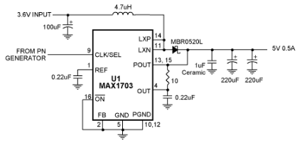
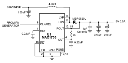
In Figure 1, the switching regulator IC (U1) has an external clock input. Driving this input with a digital signal of pseudo-random noise (PN) provides the regulator with a spread-spectrum clock that reduces EMI. By spreading interference frequencies over a wide range, this technique lowers the EMI power density that is otherwise concentrated at a single clock frequency.

Figure 1. To reduce EMI, this conventional step-up DC-DC converter employs spread-spectrum pulse-width modulation (SSPWM) produced by the PN clock input.
The PN generator (Figure 2) spreads interference over a wide spectrum. Its key element is two 8-bit shift registers (U2 and U3) connected in series to form a 16-bit shift register, with feedback from the XOR gate U4A. The result is an almost random (pseudo-random) output, consisting of a repeating sequence of ones and zeroes at a nominal frequency of 650kHz. The D flipflop (U5) divides this frequency by two, producing a nominal 325kHz spread-spectrum clock signal to the switching regulator.

Figure 2. This generator of pseudo-random noise (PN) produces a nominal 325kHz clock signal for the Figure 1 circuit.
Bench measurements show a 15dB reduction in peak power-density at about 300kHz. Except for 9mA of extra current drawn by the PN generator, the regulator's efficiency remains unchanged. (The efficiency is 94% while delivering 0.5A with a 3.6V input and 5V output.) Ripple amplitude in the time domain also remains unchanged. Output spectra show that a conventional fixed-frequency clock (Figure 3) produces considerably more noise than does the spread-spectrum technique (Figure 4).

Figure 3. This output-noise spectrum is produced by the Figure 1 circuit operating with a fixed-frequency control scheme.

Figure 4. An SSPWM control scheme produces less output noise in the Figure 1 circuit than does the conventional fixed-frequency approach.
A similar version of this article appeared in the November 5, 2001 issue of Electronic Design magazine.
Electromagnetic radiation (called electromagnetic interference or EMI when it's unwanted) is emitted by nearly all electronic systems, including switching regulators. To suppress EMI, the conventional method is to block the radiation at its source with a metallic or magnetic shielding, or both. For switching regulators, you can further enhance suppression by adopting a spread-spectrum pulse-width modulation (SSPWM) control scheme.
In Figure 1, the switching regulator IC (U1) has an external clock input. Driving this input with a digital signal of pseudo-random noise (PN) provides the regulator with a spread-spectrum clock that reduces EMI. By spreading interference frequencies over a wide range, this technique lowers the EMI power density that is otherwise concentrated at a single clock frequency.

Figure 1. To reduce EMI, this conventional step-up DC-DC converter employs spread-spectrum pulse-width modulation (SSPWM) produced by the PN clock input.
The PN generator (Figure 2) spreads interference over a wide spectrum. Its key element is two 8-bit shift registers (U2 and U3) connected in series to form a 16-bit shift register, with feedback from the XOR gate U4A. The result is an almost random (pseudo-random) output, consisting of a repeating sequence of ones and zeroes at a nominal frequency of 650kHz. The D flipflop (U5) divides this frequency by two, producing a nominal 325kHz spread-spectrum clock signal to the switching regulator.

Figure 2. This generator of pseudo-random noise (PN) produces a nominal 325kHz clock signal for the Figure 1 circuit.
Bench measurements show a 15dB reduction in peak power-density at about 300kHz. Except for 9mA of extra current drawn by the PN generator, the regulator's efficiency remains unchanged. (The efficiency is 94% while delivering 0.5A with a 3.6V input and 5V output.) Ripple amplitude in the time domain also remains unchanged. Output spectra show that a conventional fixed-frequency clock (Figure 3) produces considerably more noise than does the spread-spectrum technique (Figure 4).

Figure 3. This output-noise spectrum is produced by the Figure 1 circuit operating with a fixed-frequency control scheme.

Figure 4. An SSPWM control scheme produces less output noise in the Figure 1 circuit than does the conventional fixed-frequency approach.
A similar version of this article appeared in the November 5, 2001 issue of Electronic Design magazine.
 电子发烧友App





评论